Define the Load
Create a second boundary condition to impose a vertical displacement along the top surface of the plate.
The plate is loaded by imposed displacements because it results in a much more gradual failure process than a comparable loading by applied forces. When a simple structure, such as this composite plate, begins to fail under the action of applied forces, it fails very rapidly. This happens because the load continues to increase as the load carrying capacity of the structure decreases. With displacement controlled loading, the load carried by the structure decreases as the structure fails which allows for a slower rate of failure.
First, a coupling constraint is applied to the nodes on the top surface that allow for a simple determination of the total reaction force during post-processing.
Select Preprocessor > Coupling / Ceqn > Cupl DOFs w/Indep.
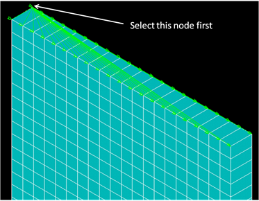
Pick all nodes on the top surface of the plate, making sure that the first node picked is the node indicated in the image below. Click OK.
Set the reference number to 20 and the degree-of-freedom label to UY. Click OK to complete the coupling definition.
As a consequence of the coupling constraint, a displacement in the y-direction applied to the node highlighted below will result in the same y-displacement applied to the remaining nodes in the constraint definition.
Select Preprocessor > Loads > Define Loads > Apply > Structural > Displacement > On Nodes and select the node indicated below.
Apply a UY value of 0.06 and click OK.