Introduction
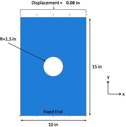
The problem consists of a flat composite plate with a hole in the center subject to fixed boundary conditions on one end, and a displacement controlled load of 0.08" (0.53% of the plate length) on the other end. The plate is made of IM7/8552, the layup is [0/±45/90]s, and the ply thickness is 0.005" which results in a plate thickness of 0.04". The seed size for the mesh is 0.2, and 8-node layered solid shell elements (SOLSH190) are used. The dimensions, boundary conditions, and load are shown below. After the model is created and the finite element analysis is completed, steps are provided to view and interpret the results.

If you are interested only in learning how to interpret results from Helius PFA, an ANSYS input file (Tutorial_3_ANSYS.ans) is available for download that can be used to generate an ANSYS results (*.rst) file. Before submitting the file for analysis, ensure the matID values in the input file match the matID for IM7_8552 on your workstation. The matID for IM7_8552 can be determined by selecting IM7_8552 in the Helius PFA plug-in within ANSYS as detailed later in this tutorial (Create a User Material with Helius PFA).
In the following tutorial, elementary modeling details are omitted. It is assumed you have previous experience in the ANSYS Mechanical environment. For example, it is assumed you know how to enter a command into the command prompt so that when an instruction tells you to enter text into the command prompt, the instructions to perform that task are omitted. Please refer to the ANSYS documentation before completing this tutorial if you are unfamiliar with the ANSYS GUI.