Create the Model Geometry
Defining the part geometry is generally the first step in the development of a finite element model.
Here, the plate geometry is defined to generate a 3-dimensional part.
Open ANSYS Mechanical APDL using the Helius PFA for ANSYS Launcher tool shown below. This tool launches ANSYS with the necessary environment variables to run Helius PFA with ANSYS.
This tool is installed with the product and is located at the following path:
%install_dir%\bin\ansys-helius-launcher.exeIt can also be found by going to Start > All Programs > Autodesk Helius PFA 2018 > ANSYS APDL Launcher, or by clicking on the desktop icon
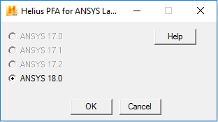
Click the Run button in the ANSYS Mechanical APDL Product Launcher. The ANSYS GUI will appear.
Click Main Menu > Preprocessor > Modeling > Create > Volumes > Block > By 2 Corners & Z.
In the dialog box that appears, enter the following values and click OK:
- WP X = 0
- WP Y = 0
- Width = 0.254
- Height = 0.381
- Depth = 0.001016
Click Main Menu > Preprocessor > Modeling > Create > Volumes > Cylinder > Solid Cylinder.
In the dialog box that appears, enter the following values then click OK:
- WP X = 0.127
- WP Y = 0.1905
- Radius = 0.0381
- Depth = 0.001016
Click Main Menu > Preprocessor > Modeling > Operate > Booleans > Subtract > Volumes.
Select the plate from the Graphics Window. A message will appear noting there are two volumes at this location. Make sure Volume 1 is the Picked Volume and click OK.
Click OK in the Subtract Volumes dialog box.
Select the cylinder from the Graphics Window. Make sure Volume 2 is the Picked Volume and click OK.
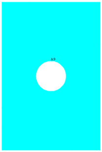
Click OK in the Subtract Volumes dialog box. The plate geometry is now defined. The plate should appear as shown below.