Create Composite Material Plug-in
Use the Helius PFA plug-in interface to choose from a variety of material and analysis options.
These options include:
- Selection of a composite material to use in the analysis (Helius PFA compatible material definitions must be created outside of ANSYS Mechanical using Composite Material Manager)
- The choice of four unit systems
- Selection of the principle material direction
- Creating additional output variables that provide fiber and matrix constituent stresses and strains
- Inclusion of progressive failure in the analysis. When this option is used, Helius PFA will degrade (reduce) the material properties when failure in the matrix or fiber is detected.
- Inclusion of pre failure nonlinearity
- Setting the matrix and fiber post-failure degradation ratios
Using these options, you can tailor the analysis to the requirements of the problem. For a detailed discussion of the options available, refer to the Helius PFA User's Guide.
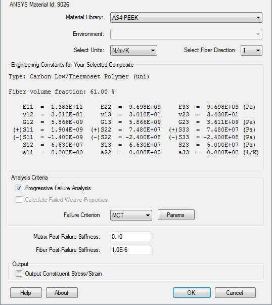
In the following steps, AS4-PEEK is defined using the Helius PFA GUI.
Click the HELIUS button from the ANSYS Toolbar and choose Create Composite Material.
Note: The HELIUS button only works in the model creation preprocessor (/PREP7).From the Material Library list, select the material AS4-PEEK.
The unit dependent Engineering Constants specific to this material are listed in the plug-in for you to review. Note the ANSYS Material ID (matID) that corresponds to this material is also shown in the dialog box. This value may vary from computer to computer.
Since this model uses meters and Newtons as base units, select N/m/K from the Select Units list.
There are 4 unit systems to choose from. The default unit system is N/m/K.
Select 1 as the fiber direction.
2 can also be used as the fiber direction, but it would require a different composite layup orientation than the 1 direction. As a general rule, it is recommended that 1 be used as the fiber direction to maintain consistency from model to model. On occasion, however, it will not be possible to create an orientation in ANSYS that allows for the 1 direction to be the fiber direction due to the combination of complex model geometry and section orientation limitations. In such cases, it may be necessary to use the 2 direction as the fiber direction.
Accept the remaining default parameters.
The plug-in should appear as shown below.
Click OK.