Define a Helius PFA Composite Material
Use the MATPFA entry to define the composite material response.
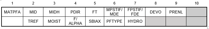
MATPFA Fields
Appendix A provides a detailed description of each MATPFA field, including the range of allowable values for each field and the impact that each field has on the multiscale constitutive relations used to represent each material. A brief description of each MATPFA field is given below.
Material Identification Number (MID) - The generic material identification number for the MATPFA material card. This number is called in the property definitions in order to associate the property with the appropriate material.
Helius PFA Material Identification Number (MIDH) - The Helius PFA Material identification number found in the HPFAMatDB.xml file in the materials directory. Refer to Appendix A.2 for details regarding the Helius PFA Material ID number.
Principal Material Coordinate System (PDIR) - Helius PFA expresses constitutive relations and computes stress in the principal material coordinate system of the composite material. The PDIR field specifies the specific orientation of the principal material coordinate system that will be used.
- Unidirectional Microstructures: The default principal material coordinate system is oriented with the '1' direction aligned with the fiber direction, while the '2' and '3' directions lie in the material's plane of transverse isotropy. This default orientation of the principal material coordinate system is selected by setting the PDIR field to a value of 1. However, in situations where it adds convenience or simplicity to the model creation process, you may change the orientation of the principal material coordinate system so that the '2' direction is aligned with the fiber direction, while the '1' and '3' directions lie in the composite material's plane of transverse isotropy. This alternative orientation of the principal material coordinate system is selected by setting the PDIR field to a value of 2. In general, the numerical value of the PDIR field identifies the specific principal material axis that is aligned with the fiber direction.
- Woven Microstructures: The default principal material coordinate system is oriented with the '1' direction aligned with the fill tow direction, while the '2' direction corresponds to the warp tow direction and the '3' direction corresponds with the out-of-plane direction. This default orientation of the principal material coordinate system is selected by setting the PDIR field to a value of 1. However, in situations where it adds convenience or simplicity to the model creation process, you may change the orientation of the principal material coordinate system so that the '2' direction is aligned with the fill tow direction, while the '1' direction corresponds to the warp tow direction. This alternative orientation of the principal material coordinate system is selected by setting the PDIR field to a value of 2. Additionally, you may change the orientation of the principal material coordinate system so that the '3' direction is aligned with the fill tow direction while the '2' direction corresponds to the warp tow direction. This particular orientation of the principal material coordinate system is selected by setting the PDIR field to a value of 3. In general, the numerical value of the second user material constant identifies the specific principal material axis that is aligned with the fill tow direction.
Failure Theory (FT) - The FT field is the failure theory flag. The failure theory flag specifies the criterion to use to evaluate failure initiation in the composite material. The default value is MCT. Other valid options are:
- STRESS - Max Stress
- STRAIN - Max Strain
- HILL (unidirectional only) - Tsai-Hill
- TSAI (unidirectional only) - Tsai-Wu
- CHRIS (unidirectional only) - Christensen
- HASH (unidirectional only) - Hashin
- PUCK (unidirectional only) - Puck
- LaRC02 (unidirectional only) - LaRC02
- USER - User-defined
Matrix Post-Failure Stiffness (MPSTIF) / Matrix Degradation Energy (MDE) - For analyses not using Energy-Based Degradation, the MPSTIF field is a fraction used to define the damaged elastic moduli of the matrix constituent after matrix constituent failure occurs. Specifically, the value is the ratio of the failed matrix constituent moduli to the unfailed matrix constituent moduli. A value of 0.1 would mean that after a matrix failure occurs at an integration point, all six of the matrix constituent moduli (
 ,
,  ,
,  ,
,  ,
,  ,
,  ) are reduced to 10% of the original undamaged matrix constituent moduli. The matrix post-failure stiffness value must be greater than 0, and less than or equal to 1. By default, the matrix post-failure stiffness value is set to 0.1.
For analyses using Energy-Based Degradation, the MDE field is the total energy dissipated before and after a matrix failure assuming a linear degradation of composite stiffness after a failure event. Specifically, composite
 ,
,  ,
,  ,
,  , and
, and  are degraded after a matrix failure event according to this energy, the composite stress state at fiber failure, and the volume of the element.
Fiber Post-Failure Stiffness (FPSTIF) / Fiber Degradation Energy (FDE) - For analyses using instantaneous degradation, the FPSTIF field is a fraction used to define the damaged elastic moduli of the fiber constituent after fiber constituent failure occurs. Specifically, the value is the ratio of the failed fiber constituent moduli to the unfailed fiber constituent moduli. A value of 0.01 would mean that after a fiber failure occurs at an integration point, all six of the fiber constituent moduli (
 ,
,  ,
,  ,
,  ,
,  ,
,  ) are reduced to 1% of the original undamaged fiber constituent moduli. The fiber post-failure stiffness value must be greater than 0, and less than or equal to 1. The default value of the fiber post-failure stiffness is automatically set to 1E-06.
For analyses using Energy-Based Degradation, the FDE field is the total energy dissipated for a fiber failure assuming a linear degradation of composite stiffness before and after a fiber failure event. Specifically, composite
 , , and are degraded linearly after a fiber failure event according to this energy, the composite stress state at fiber failure, and the volume of the element.
Damage Evolution Method (DEVO) - The DEVO field allows you to select either the Instantaneous or Energy-Based damage evolution methods. A value of INSTANT activates Instantaneous Degradation and a value of EBD activates Energy-Based Degradation.
- Instantaneous Degradation: If the instantaneous degradation feature is activated, Helius PFA will instantly reduce the stiffness of the composite moduli to their minimum values. It should be emphasized that an instantaneous reduction of the stiffness of a failed constituent effectively results in a discontinuous, piecewise linear stress/strain response for the constituent and the composite. However, when this type of discrete material response is applied independently at each of the integration points in a large finite element model, the net result is a gradual (or progressive) degradation of the overall stiffness of the composite structure (hence the name Progressive Failure Analysis).
- Energy-Based Degradation (unidirectional materials only): If the Energy-Based Degradation feature is activated, Helius PFA will gradually reduce the stiffness of the composite moduli to their minimum values in a linear fashion after a failure event has been detected while conserving the energy given in the MDE and FDE fields. After a failure criterion is triggered, the composite stiffness is gradually reduced via a series of discrete stiffness reductions that are applied as the composite strain state continues to increase beyond the level present at failure initiation. The specific stiffness that is affected depends entirely on the constituent failures that have been triggered. This feature is only compatible with the MCT failure criterion and unidirectional materials.
Pre-Failure Nonlinearity (PRENL) - The PRENL field activates or deactivates the product's pre-failure nonlinearity feature. It is an optional flag, available only for composites that use the MCT failure criterion. A value of ON activates the pre-failure nonlinearity feature, while the default value of OFF deactivates the pre-failure nonlinearity feature. If the pre-failure nonlinearity feature is activated, Helius PFA will explicitly account for the nonlinear longitudinal shear stress-strain response that is typically observed in fiber-reinforced composite materials. The pre-failure nonlinearity feature imposes a series of discrete reductions in the longitudinal shear stiffness of the matrix constituent material, causing the composite material's nonlinear longitudinal shear response to closely match experimentally measured data. It should be emphasized that the pre-failure nonlinearity feature only affects the longitudinal shear moduli of the composite (i.e.,
 vs.
vs.  , and
, and  vs.
vs.  ), while the responses of the other four composite stress and strain components remain unaffected by this feature. Also, the pre-failure nonlinearity feature will not alter the shear stress level at which the composite fails; however, it will result in an overall increase in longitudinal shear deformation of the composite prior to failure.
Temperature (TREF) - The TREF field is used to specify the temperature value that corresponds to the environment in the material data file (mdata file) to be used in the analysis. For example, if the mdata file contains environments characterized at 600, 650, and 700 R, and the value of the TREF field is 650, then the properties stored at 650 R will be used in the analysis. The temperature value, along with the moisture flag (MOIST field) are used to fully specify the environment to be used in the analysis. If the mdata file contains a single set of properties, the TREF field can be left blank.
If the value of the TREF field is set to -1.0, the temperature dependence feature will be activated. When temperature dependence is active, the product linearly interpolates the composite and constituent properties for any given temperature that lies within the bounds of the lowest and highest temperature points stored in the material file. For temperatures below the lowest stored temperature datum, Helius PFA will use the material properties stored at the lowest temperature datum (it will not extrapolate properties beyond the bounding stored temperature data points). The same is true for temperatures above the highest stored temperature datum. For further information on the use of temperature dependent material properties in Helius PFA, refer to the Theory Manual.
Moisture (MOIST) - The MOIST field is used to specify the moisture flag that corresponds to the environment in the material data file (mdata file) to be used in the analysis. Available options are AMBIENT, DRY, and WET. By default, MOIST is set to AMBIENT. For example, if the mdata file contains environments characterized at ambient, wet, and dry moisture conditions, and the value of the MOIST field is set to DRY, the properties for the dry moisture content(s) will be used in the analysis. The moisture flag, along with the temperature value (TREF) are used to fully specify the environment to be used in the analysis. If the mdata file contains a single set of properties, the MOIST field can be left blank.
Auxiliary Criterion Parameter 1 (F/ALPHA) - Used to specify parameters for some of the auxiliary failure criteria. If Tsai-Wu is selected, this constant represents the cross product term, f*. If Hashin is selected, this constant represents the contribution of longitudinal shear stress to the fiber failure criterion, α.
Auxiliary Criterion Parameter 2 (SBIAX) - Used to specify the equibiaxial stress at failure (σ11 and σ22 combined) for the Tsai-Wu failure criteria. This value can be left as zero if it is unknown.
Type of Progressive Failure Analysis (PFTYPE) - The PFTYPE field activates or deactivates the product's progressive failure analysis feature. If the progressive failure feature is activated, Helius PFA will degrade the element stiffness according to the selected damage evolution method if failure is predicted by the selected failure criterion. If this feature is deactivated, then the element stiffness remains constant throughout the entire analysis. This is often referred to as a linear analysis.
- Unidirectional Microstructures: A value of 1 activates the progressive failure analysis feature, while a value of 0 deactivates the progressive failure analysis feature.
- Woven Microstructures: A value of 0 deactivates the progressive failure feature. A value of 1 activates the progressive failure feature and uses the matrix and fiber degradation levels from the material data file to calculate the failed material properties. A value of 2 activates the progressive failure feature and uses the matrix and fiber degradation levels specified by the MPSTIF/MDE and FPSTIF/FDE fields to calculate the failed material properties. Selecting a value of 2 will add approximately 45-60 seconds to the pre-processing time per woven material. A value of 1 will not add run-time during pre-processing because the failed material properties are already stored in the material file.
Hydrostatic Strengthening (HYDRO) - The HYDRO field is an optional field only available for unidirectional composites that use the MCT failure theory. It activates or deactivates the product's hydrostatic strengthening feature. A value of ON activates the hydrostatic strengthening feature, while the default value of OFF deactivates the hydrostatic strengthening feature. If the hydrostatic strengthening feature is activated, Helius PFA explicitly accounts for the experimentally observed strengthening of the composite in the presence of a hydrostatic compressive stress. If the hydrostatic compressive stress in the matrix constituent exceeds a threshold value, the strength of both the matrix constituent and the fiber constituent are scaled upwards commensurate with the level of hydrostatic compressive stress level in the matrix constituent.