Shape Generator uses applied loads to determine the resultant shape of the part.
Changing the loads applied to your part will likely produce a different shape.
Load Types
- Force (N or lbforce)

- Apply to a set of faces, edges, or vertices. The force points to the inside of the part. Define the direction planar faces, straight edges, and axes.
By default, Force is applied:
- Normal to the selected face.
- Parallel with the selected edge.
- Using the vector components in the expanded section of the dialog box.
- Pressure (MPa or psi)

- Apply only to faces. Pressure is uniform and acts normal to the surface at all locations on the surface.
- Bearing load (N or lbforce)

- Apply only to cylindrical faces. By default, the applied load is along the axis of the cylinder and the direction of the load is radial. Forces are predominantly
- Radial (roller bearing)
- Perpendicular to axis (moment)
- Moment (N*m or lbforce in)

- Apply only to faces. Define direction using planar faces, straight edges, two vertices, and axes. Apply around the axis and perpendicular to the face.
- Gravity

- Face or Edge. Specifies the direction of gravitational load on the model. Select a face to define the direction or use Vector Components to control the direction precisely. Cylindrical selections provide an axial direction.
Apply gravity of the specified magnitude normal to the selected face or parallel with the selected edge.
Vector components define the magnitude and direction of gravity.
- Remote Force (N or lb)

- Use remote force to:
- Apply a force at a specific point outside or inside of the model.
- Be transformed as an equivalent force and moment on a given face.
Apply a force of the specified magnitude to the selected face.
- Body

- Specifies the linear acceleration for the model using a face as input. Cylindrical selections provide an axial direction. You can only apply one body load per Shape Generator study.
Apply linear acceleration or angular velocity and acceleration of the specified magnitude to the model:
- Linear Face or edge. Loads are applied perpendicular to the face with the magnitude value. Positive values are applied into the face. Loads are applied parallel to edge selections.
- Angular Face or edge. Apply angular velocity and acceleration of the specified magnitude normal to a face or parallel to an edge
- Location Vertex. Specifies an alternate location for the body loads. The location is shared between velocity and acceleration.
Apply load
- In the Loads panel, click the load type to apply, or in the browser, right-click the Loads node
 and click the appropriate load type .
- With the selector command active, select inputs in the graphic area. Based on the load type, make the corresponding selection.
When selecting more than one input, all inputs must be the same entity type.
- The selection displays a glyph indicating the direction in which the load is applied. To change the load direction, describe the direction using the vector components in the expanded section (for applicable load types).
- The More section of the dialog box also provides the glyph settings for that load. Adjust the glyph settings, if necessary.
Edit load
- In the browser, double-click the load node
or
- Right-click the load node, and click Edit [type] constraint.
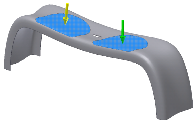
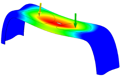
Split faces for load application
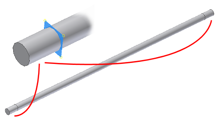
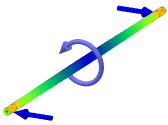
In many applications, different locations on a component surface are subject to different loads. An example is a rotating shaft supported at both ends by bearings. The middle section of the shaft is under a moment, while the ends of the shaft see bearing loads.
When you assign bearing loads to components, such as a shaft, you can split faces to create bearing contact locations.
Another example is the application of loads to simulate two individuals seated on a park bench. Split the top bench surface to create locations where you can apply the weight of the individuals.