Designing Spur Gear Backlash Allowance
Backlash types (defined for each gear in a gear set)
Real gears must be manufactured with a specific backlash allowance. Designate the allowance by considering the machining and working conditions.
In spur and helical gearing, there are two alternate ways to obtain the appropriate amount of backlash. First, decrease tooth thickness by sinking the hob deeper into the blank than the theoretical standard depth is. Second, increase the center distance than theoretically computed.
When designing a backlash, consider following factors:
- Lubricant space required.
- Differential expansion between the gear components and the housing.
- Errors in machining. Run-out of both gears, errors in profile, pitch, tooth thickness, helix angle and center distance. The smaller the amount of backlash, the more accurate the machining of the gears is.
- Working conditions such as frequent reversing or overrunning load.
The amount of backlash must not be excessive for the requirements of the job. Ensure it is sufficient so that machining costs are not higher than necessary.
It is customary to make half of the allowance for backlash on the tooth thickness of each gear of a pair, although there are exceptions. For example, on pinions having low numbers of teeth, it provides all the allowance on the driven gear. It avoids weakening the pinion teeth.
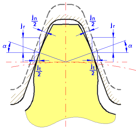
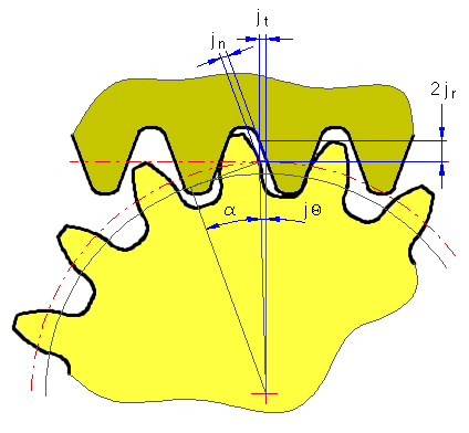
- Circular backlash jt [mm/in]
- Normal backlash jn [mm/in]
- Center backlash jr [mm/in]
- Angular backlash jΘ [deg]


 |  |
Backlash of Helical Gear Mesh
The helical gear has two kinds of backlash when referring to the tooth space. There is a cross section in the normal direction of the tooth surface “n”, and a cross section in the transverse direction perpendicular to the axis “t”.
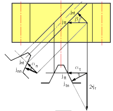
In the plane normal to the tooth: | j nn = j nt cos α n |
On the pitch surface: | j nt = j tt cos β |
In the plane perpendicular to the axis
jtn = jtt cos αt

where:
| α | Pressure angle |
| α n | Pressure angle in normal direction, α = α n |
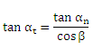
| α t | Pressure angle in transverse direction |
| β | Helix angle |
| d | Pitch diameter |