To Edit iParts
You can add parameters, edit the iPart spreadsheet, convert iPart to part, and edit bend order.
In the browser, the default iPart member is marked with a check mark
Edit iPart Table
Click File
 Open.
Open.Browse to locate the iPart factory file, and then click Open.
In the browser, click to expand the table folder. The default iPart member is marked with a check mark.
Right-click the table icon and select Edit Table.
In the iPart Author table, change values as needed. You can also right-click and select:
- Insert Row to add another member of the iPart.
- Delete Row to remove a member of the iPart.
- Set as Default Row when the iPart is placed. (If you're using Inventor, set as Default Row to insert this version in an assembly automatically when the iPart is placed.)
- Custom Parameter Column to allow a value to be entered in all members when the iPart is placed.
- Custom Parameter Cell to allow a value to be entered only when this member of the iPart is placed.
- Delete Column to remove the parameter or property from all members of the iPart.
Click OK to close the dialog box and then save the file.
Add Parameters
As you dimension the part, create parameters by typing in the name of the parameter followed by the value. For example, Length=75mm.
On the ribbon, click 3D Model tab
 Show Panel icon
  . Select Parameters panel , and then select Parameters
Determine which parameters and properties to change with each member. Rename parameters with descriptive and recognizable names.
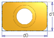
 In this example, dimensions display as d0 and d1. You can create the parameters Length and Width as you add these dimensions, or open the Parameter table and rename them to Length and Width.
Create relationships with other parameters as needed. For example, set the cylinder hole center position to length/2 or width/2. In the graphics window, fx precedes parameters that are defined by relationships to other parameters.
As you create or edit features, you can enter parameter names or equations in the dimension dialog box or in the feature dialog box.
Save the file.
Edit iPart Spreadsheet
Values calculated by equations in the spreadsheet are shown with a red background in the iPart table.
Click File
 Open.
Open.Browse to locate the iPart factory file, and then click Open.
In the browser, click to expand the table folder.
Right-click the table icon and select Edit via Spreadsheet. The iPart table opens in Microsoft Excel.
Edit cells as necessary, but do not change the column headings. Changed column headings cause all members of the iPart to fail to compute.
Use Microsoft Excel tools, as needed. For example:
- Copy and paste rows to add new members of the iPart. Change only needed cells to differentiate between iPart versions.
- Use formulas to create the data.
- Sort the data to organize it in a logical way, such as sorting on a critical value in ascending or descending order.
Save the spreadsheet and close it.
Insert members into an assembly file to test the new data. If an information icon is displayed in the assembly browser, there are errors in the member. Reopen the spreadsheet and make corrections.
Tip: To help find problems, repeat this process for each new parameter or property or changed data.Note: If you wish to discard changes after saving, click Undo.
Convert iPart to Part
- Click File
 Open.
Open. - Browse to locate the iPart factory file, and then click Open.
- In the browser, right-click the table folder and select Delete.
- A message warns you that deleting the table converts the iPart to a normal part. Click OK to convert.
- Save the part.
Edit Bend Order
- Create a sheet metal part that you expect to use as an iPart factory.
- In the sheet metal part, create the Flat Pattern representation.
- On the ribbon, click Manage tab
 Author panel
  Create iPart.
 - Create individual iPart rows representing the various members of your iPart factory.
- Once you have added all of the member rows, click OK to save the factory table.
- In the part browser, click to expand the table folder.
- Activate the iPart member for which a unique bend order is to be applied.
- In the browser, right-click the Flat Pattern node and click Go to Flat Pattern.
- In the Flat Pattern tab
 Manage panel
  click Bend Order Annotation.
 - In the canvas, click and modify each bend number that you want to adjust. Use the Unique Number option unless more than one bend occurs in the operation.
- Right-click in the canvas and click OK.
- Repeat steps 7 through 11 for each member of the factory that require a unique bend order sequence.