To Work with Text and Leaders
Use the text commands to add leader text and note text to the 3D model.
What's New: 2021, 2022, 2023, 2024.1, 2025
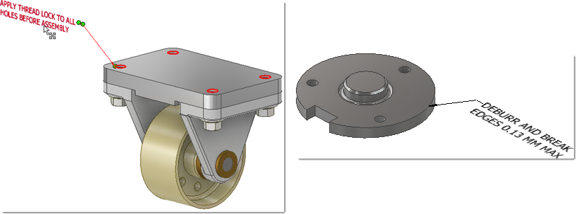
Add or edit a leader line with text
Leader Text is created with a single-segment leader by default. To create more leader segments, start the command, right-click, and click Single-Segment Leader to unselect the option.
On the ribbon, click Annotate tab
 Notes panel Leader Text
  .
.Select the anchor point on the geometry.
Optionally, right-click and do any of the following:
Click Change to Next Candidate Plane in the context menu or use the SPACEBAR shortcut to cycle through alternate planes.
Click Change Annotation Plane and then select a planar face to orient the text.
Click Toggle Alignment to reorient the text.
Click Align to Geometry in the context menu and then select an edge or axis to orient the text.
Click Add Vertex to include an additional vertex in the leader, providing more flexibility for the leader shape.
Click Delete Vertex to remove vertices that were added to the leader.
Click Add/Remove Associated Geometry and then select the geometry you want to associate with the leader text.
Tip: You can use window select to add or remove geometry. After creation, highlight the leader line to view the associated geometry.
Click to place the leader endpoint.
Add the desired text in the Format Text dialog box and then click OK or Apply to create.
After creation, highlight the leader line to view the associated geometry.
To edit leader text do one of the following:
- Select the leader in the display or browser, right-click, and select Edit in the context menu.
- Double-click the leader in the display or browser.
Change the required values, add or remove associated geometry, and then click OK.
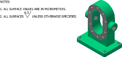
Add a General Note
On the ribbon, click Annotate tab
Notes panel General Note  .
.Select the quadrant in the display to place the note.
Add the desired text in the Format Text dialog box.
If desired, click the Insert Surface Texture icon
 to add a general surface texture to the note.
You can also click
 to add a general profile to the General Note.
Click OK or Apply to create.
The note is displayed normal to the view.
Add a General Profile Note
A General Profile Note adds control for faces not identified with a tolerance feature annotation.
On the part ribbon, click Annotate tab
Notes panel General Profile Note  .
.Select the quadrant in the display to place the note.
In the note text, select <<$GENERAL_PROFILE_TOL>> and then click the Insert General Surface Profile Tolerance icon
to specify the tolerance value and to associate to a DRF.Add the desired text in the Format Text dialog box and then click OK or Apply to create.
The note is displayed normal to the view.
A General Profile in the note participates in a Tolerance Advisor analysis.
Edit a Note
To edit a General Note or a General Profile Note:
Locate the note in the browser, right-click, and select Edit.
Tip: If you set the selection filter in the QAT to Select Annotations, you can double-click a note in the display to edit.To edit a surface texture, click inside the <<$GENERAL_SURFACE_SYM>> text, then click the Edit Surface Texture icon
to edit the surface finish requirements.To edit a general profile, do one of the following:
- Click inside the <<$GENERAL_PROFILE_TOL>> text, then click the Edit General Surface Profile Tolerance icon to change the tolerance value or associate to a DRF.
- Click inside the <<$GENERAL_PROFILE_TOL>> text, right-click, and select Edit Profile Tolerance in the context menu. Change the tolerance value or associate to a DRF.
- Click inside the <<$GENERAL_PROFILE_TOL>> text, then click the Edit General Surface Profile Tolerance icon
After you make the desired changes, click OK.
Display Instance Properties as Leader Notes
Instance properties are properties assigned to individual component instances that are stored in the parent assembly. Unlike iProperties, instance properties don't affect the referenced component files. To learn how to display instance properties as leader notes, see To Work with Instance Properties.