When you connect to a feature source, your map is a window onto the data. Your edits are made directly to the source. The data remains in its source location. Any changes you make appear in the source. Any changes in the source are immediately reflected in your map.
When you edit objects from attached drawings, AutoCAD Map 3D toolset tracks the original location of each object and saves them back to their original source.
Use AutoCAD Tools to Edit All Data
Use the full set of AutoCAD editing tools and commands to add or change map objects. It does not matter what the object source is. Editing does not convert the data. AutoCAD Map 3D toolset includes all the AutoCAD editing tools as well as tools designed for creating maps, such as using coordinate geometry to specify a point. View and style with the ease of GIS, edit with the power of CAD.

Use the powerful, high-precision AutoCAD tools to edit a feature, then save your changes back to the data source.
Lock Data for Secure Editing
For geospatial features, you can choose how to save your changes. Set an option to save changes to the original source automatically, or work offline and update the feature source when you finish editing. Check out a feature to lock it for other users (if the feature source supports this option). Check it back in to make it available again.
For drawing objects, you can lock the source drawings so no one else can use them. You can use save set options to control whether your changes are saved back to the original drawings or affect the current map only.

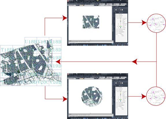
Drawing objects selected for editing in a save set (the red circle in the illustration) are locked so others cannot edit them.
| Spatial Data Type | Locking Capability |
|---|---|
| Oracle | Individual features are locked when you check them out. |
| Attached drawings (DWG) | Individual objects are locked when you query them into the map. |
Clean Up Drawings
Using Drawing Cleanup tools, you can automate the correction of common drafting and digitizing errors. Delete duplicates, correct undershoots and dangling objects, and more.

Review, mark, and correct errors interactively.
Use Coordinate Geometry Commands
Create and measure simple coordinate geometry (COGO) for lines, curves, closed polylines, and polygons. When drawing plats and existing conditions, input geometry in terms of bearing, direction, deflection, and azimuth angle.

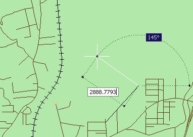
Use the Deflection And Distance COGO command to specify a point by supplying a deflection angle and a distance from another point.
Use the COGO Input dialog box to enter coordinates manually or select them in the drawing or in the Data Table. The Inverse Report option gives you information about the relationship between existing points.
Tell me more
|
|
|
|
|
|
|
|
 Procedures
 Tutorial
 Related topics
 Video
Video