
Analysis tab
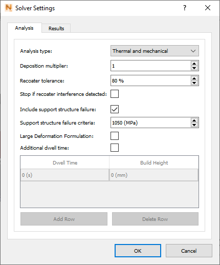
Analysis Type can be either Thermal only or both Thermal and Mechanical.
Use the Deposition Multiplier to increase the timing so as to add the time required to build multiple identical parts on the build plate. For example, if there are 12 identical parts on the build plate, and you want to simulate only 1 of the parts, enter a value of 12 for a machine with a single laser. Non-integer values are allowed for the simulation of multiple non-identical parts. If multiple lasers have been enabled in the Machine settings the system automatically adjusts the Deposition Multiplier setting to adjust the deposition time for multiple parts and multiple lasers.
Recoater Tolerance is used to set the minimum required clearance between the previous build and the recoater blade. The default value of 80% means that the recoater blade can safely deflect upward into 20% of the next layer, but if it goes higher, a Recoater Clearance warning is issued. For more information, see About Recoater Tolerance.
Stop if recoater interference detected ends the simulation if the built part deflects upward far enough to exceed the specified Recoater tolerance.
The Include support structure failure criteria option is available only if support structures are present for the simulation. If selected, the simulation will include warnings when the stress experienced by a support structure element exceeds the failure stress value (in MPa), entered in the Support structure failure criteria field.
The Large Deformation Formulation option should be selected only if your model is likely to buckle or exhibit very large deformations during manufacture. This option permits larger deformations, but takes longer to run.
If Additional dwell time is selected, you can populate table rows with the duration in seconds to pause at specified build heights for operations such as refilling powder or machining during a hybrid printing process. Each build height value must be higher than the value in the row above.
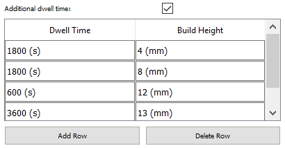
If you click Delete Row for this table, the bottom row is deleted, regardless of cursor position.
Results tab
Turn structural plasticity on or off, choose results writing options, and select the desired stress and strain result types.
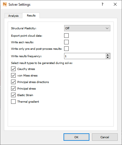
Structural Plasticity does not apply to Thermal analysis, but if you selected Thermal and Mechanical on the Analysis tab, two options are available:
- Off provides qualitative stress results throughout the processing and post processing simulation. The material is not permitted to yield when loaded, which results in very high and nonphysical stress buildups. When the part is cut from the build plate in the analysis, there will be an excessive prediction of deformation due to the release of the large stresses.
- On provides quantitative stress results after part cool down. This setting produces smaller displacement results, and more accurate stress results. It adds a plasticity step to the end of the analysis, after the part has cooled down to the final temperature and before it is removed from the build plate.
| Structural Plasticity On | Structural Plasticity Off |
|---|---|
| Accurate Distortion during deposition model | Accurate Distortion during deposition model |
| Accurate Distortion Post Bolt Release and Post EDM | Simulates in less time than with Structural Plasticity On |
| Accurate Stresses post deposition, No stresses recorded during deposition modeling | Qualitative Stress results available during deposition modeling |
Used for:
|
Used for:
|
For each selection, you can use check boxes to turn off any unwanted result types.
Select Export point cloud data if you want the system to export a series of 3D data files of the surface nodal simulation results, for post processing. Depending on your structural plasticity setting, you will get some or all of the following files:
| File extension | Result type |
| .wrtu | Nodal displacement results |
| .wrtu.epp | Nodal plastic strain results |
| .wrtu.ept | Nodal elastic strain results |
| .wrtu.eqp | Nodal equivalent plastic strain results |
| .wrtu.sd3 | Nodal principal stress results |
| .wrtu.sig | Nodal Cauchy stress results |
| .wrtu.sp3 | Nodal principal stress direction results |
| .wrtu.svm | Nodal Von mises stress results |
| .wrtu.tmp | Nodal temperature results |
| wrtu_1 | wrtu_2 | wrtu_3 | |
|---|---|---|---|
| No support structures
Fix the build plate base |
After process simulation has completed and part has cooled to final temperature | After part has been removed from the build plate | X |
| No support structures
Simulate bolt release |
After process simulation has completed, part has cooled to final temperature, and bolt release has been simulated | After part has been removed from the build plate | X |
| Support structures
Fix the build plate base |
After process simulation has completed and part has cooled to final temperature | After part and support structure have been removed from the build plate | After support structures have been removed |
| Support structures
Simulate bolt release |
After process simulation has completed, part has cooled to final temperature, and bolt release has been simulated | After part and support structure have been removed from the build plate | After support structures have been removed |
Select Write ascii results if you want the content of result files <project>.geo, <project>.geoc, and <project>.ens to be in ASCII rather than binary format. ASCII results can be useful in custom optimization routines.
The format of the data follows the EnSight Gold format. A documentation is available here: https://dav.lbl.gov/archive/NERSC/Software/ensight/doc/Manuals/UserManual.pdf
Use the Write only pre- and post-process results option to minimize the number of results saved from the simulation, which reduces the use of disk space. The Write results frequency option offers a more adjustable way to reduce the number of process steps recorded and saved. A value of 1 will write results every step, which is the default setting. A value of 2 will record every other step, 3 every third step and so on. This setting only applies to the process simulation steps. From the cooldown step onward, all post-processing steps, including heat treatment if enabled, will be written.
Select Thermal gradient if you want the results to include a thermal gradient of temperature change per unit length.