
Specify the meshing approach, mesh density settings, and multiple STL padding tolerance.
The Padding Tolerance setting applies to both meshing approaches. It is used to fill gaps that may occur between part and support structure, or any situation where multiple geometries are in contact. If gaps appear along the interface after the geometries have been meshed, increase the padding tolerance value, and each STL file will be expanded in all directions by this amount. Keep this tolerance value as small as possible to maintain dimensional accuracy of the original geometry.
Layer based
This Meshing approach provides advanced users with direct control over the mesh by using the settings Coarsening generations and Layers per element.
Coarsening generations is the maximum allowable number of coarsening steps taken. Coarsening only applies to layers below the deposition layer. When coarsening is enabled, small elements are used to represent fine detail in critical areas, which is determined by the Layers per element control detailed below. Larger elements are used on the build plate and areas with lower detail requirements by combining smaller elements together, where the geometry allows. Typical settings are from 0 to 2. A setting of 1 is generally a good compromise between speed and accuracy. A value of 2 should be used only for large geometries that have large surface areas in the build plane, while also having fine features that need to be captured.
Layers per element represents the number of powder layers in the thinnest element of the part. The size of the smallest element is equal to Layers per element X the powder bed deposition thickness contained in the PRM file. More layers per element produce a coarser mesh, and faster run time. Fewer layers per element are needed to represent finer details, but both run time and memory usage may increase dramatically. It is recommended the lowest value used is 5.
Wall thickness
This Meshing approach is the more automated method. Selecting this approach requires two inputs:
Minimum wall thickness should be set to the thinnest cross section of the imported model or models. A larger thickness value produces a coarser mesh that will simulate faster; a smaller value produces a more accurate mesh, but the run time will be increased.
Accuracy controls the number of elements per minimum wall thickness and the number of mesh coarsening generations allowed. The four options shown in the following table allow for a number of choices that balance model accuracy with speed of rendering:
| Accuracy | Elements per minimum wall thickness | Coarsening generations |
|---|---|---|
| Most Accurate | 4 | 0 |
| Accurate | 3 | 1 |
| Fast | 2 | 2 |
| Fastest | 2 | 2 |
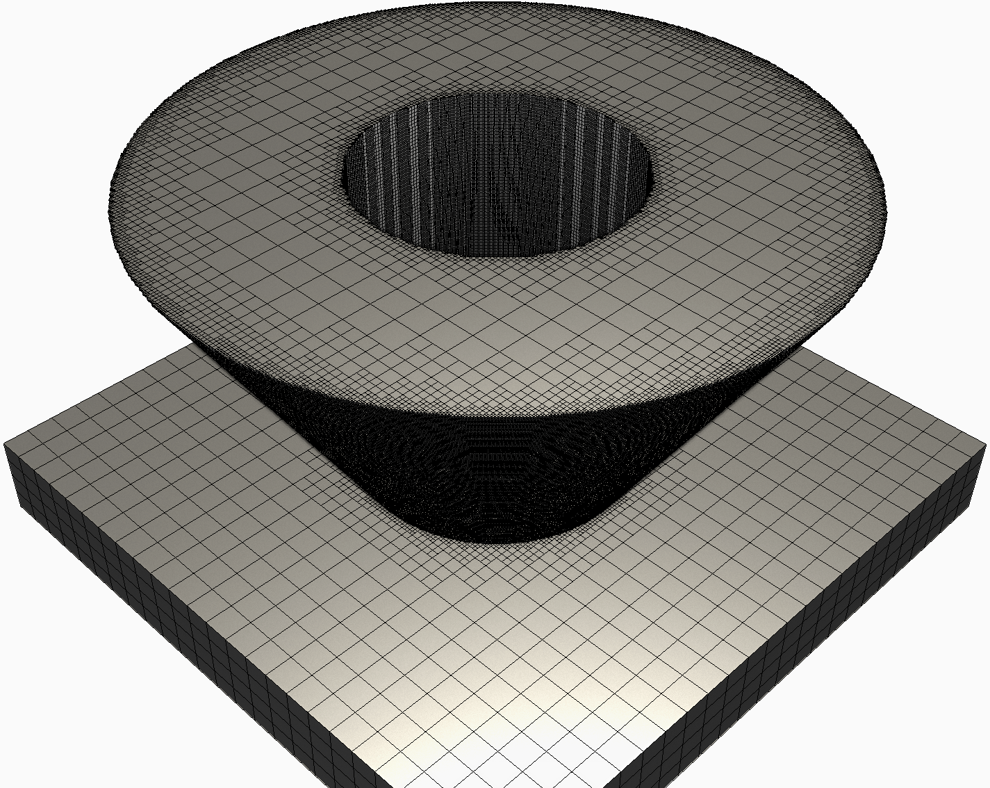
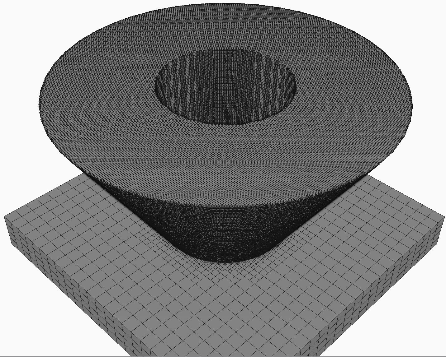
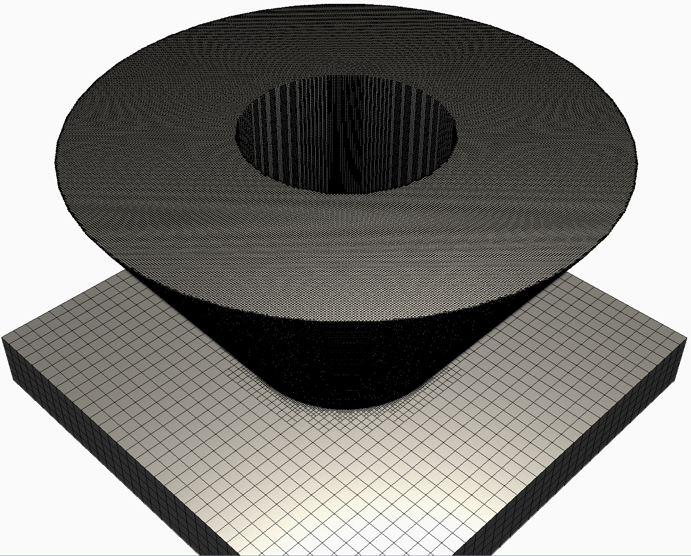
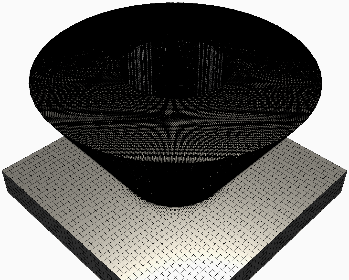
The results of the four meshing approaches for small geometry are shown below, with each mesh figure clipped around 90% of the maximum height of the part, to show the interior of the mesh, where coarsening is allowed:
| Fastest | Fast | Accurate | Most Accurate |
|---|---|---|---|
|
|
|
|
| 894468 Nodes | 894468 Nodes | 1824744 Nodes | 3621073 Nodes |
| 22361700 Elements | 460488 Elements | 971538 Elements | 1917649 Elements |
| 4430 s Projected run time | 7530 s Projected run time | 41900 s Projected run time | 207000 s Projected run time |
Mesh Quality and Convergence Metrics
At a minimum, meshes should have two elements through every cross-sectional area, which allows the mesh to deform. This is easiest to check by referencing the thinnest section and ensuring it has at least two elements. Depending on the geometry and processing parameters, more elements may be required to achieve convergence. It is suggested, as part of good FE practice, to always perform a three-part mesh convergence study.
To perform a mesh convergence study
- Solve the geometry with a coarse mesh. It is suggested to start with mesh settings that achieve the two element per thickness minimum, if practicable for the geometry size, complexity, and installed memory.
- Determine the location of peak distortion. Using the Probe Results tool, make a note of the location and record the peak value of displacement in the plane of highest distortion, X, Y, or Z. Do not use magnitude.
- Select finer mesh settings and solve again. Record the displacement value at the same location.
- Select even finer mesh settings and solve again. Record the displacement value at the same location.
- Calculate the percent difference from coarse to fine and fine to finest. If the percent difference for sets or from the fine-to-finest set, is 5% or less, the mesh has converged.
- If the mesh hasn't converged, continue to reduce the mesh density until the convergence criteria has been satisfied.
Observable poor mesh settings from results
From time to time magenta or purple results may be observed in the results as in this figure: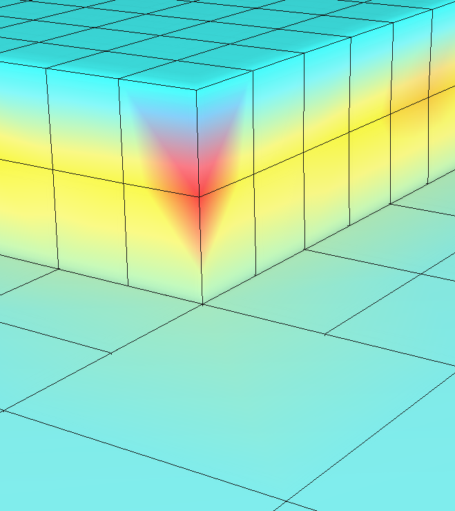
This occurs whenever the range of the display result spans from the lowest to highest in a single element. This typically indicates that the mesh used is not fine enough for the simulation geometry and settings and that one should decrease the number of layers per element.
Mesh Settings limitations of Simulation Utility
Users with Simulation Utility installed have the following limitations imposed in the Mesh Settings dialog:
- Meshing approach is limited to Layer Based.
- Coarsening generations has an upper limit of 2 (same as for Local Simulation).
- Layers per element has an upper limit of 20.
Furthermore, after the mesh is generated, either as a part of the Mesh Preview or beginning of a Solve, the simulation is stopped and the user is warned if the following mesh limits are exceeded:
- Number of nodes greater than 5 million
- Layer-Nodes (Number of grouped layers × Number of nodes) greater than 200 million