Introduction
In this exercise, we will conduct a linear static stress analysis of a simple lever arm part. We will use boundary conditions often found in entry-level CAD-based simulation systems. Note that in later exercises we will build on the steps performed here to refine the analysis setup and improve the overall accuracy of the simulation.
The model is a lever arm as shown:
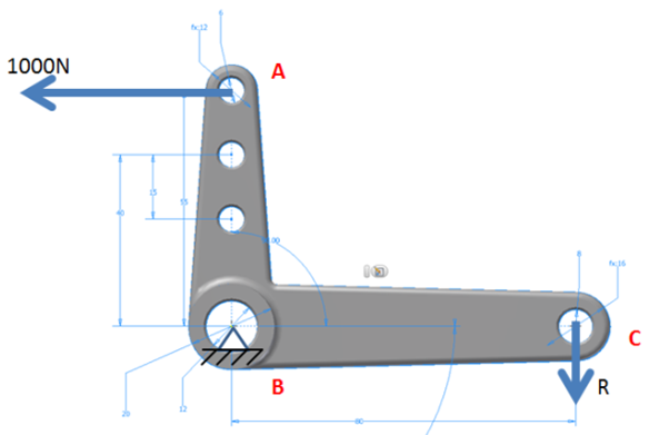
- A 1000 N load is applied to the top-most hole (A).
- The lever is pinned at the center (B).
- We assume a rod passes through hole (C) and is locked against movement.
- The reaction force, R, balances the loads, so the part is in static equilibrium. A force summation results in R = 687.5 N.
1. Open the Model and Start the Autodesk Inventor Nastran Environment
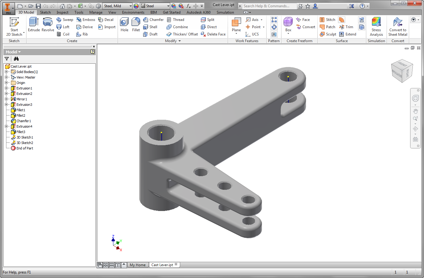
Start Autodesk Inventor, and open Cast Lever.ipt from the Section 5 - Cast Lever sub-folder of your training exercises folder. (Get Started > Launch > Open).
You should see this:
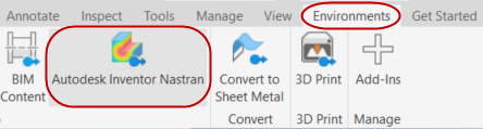
From the ribbon, click the Environments tab, and click Autodesk Inventor Nastran:
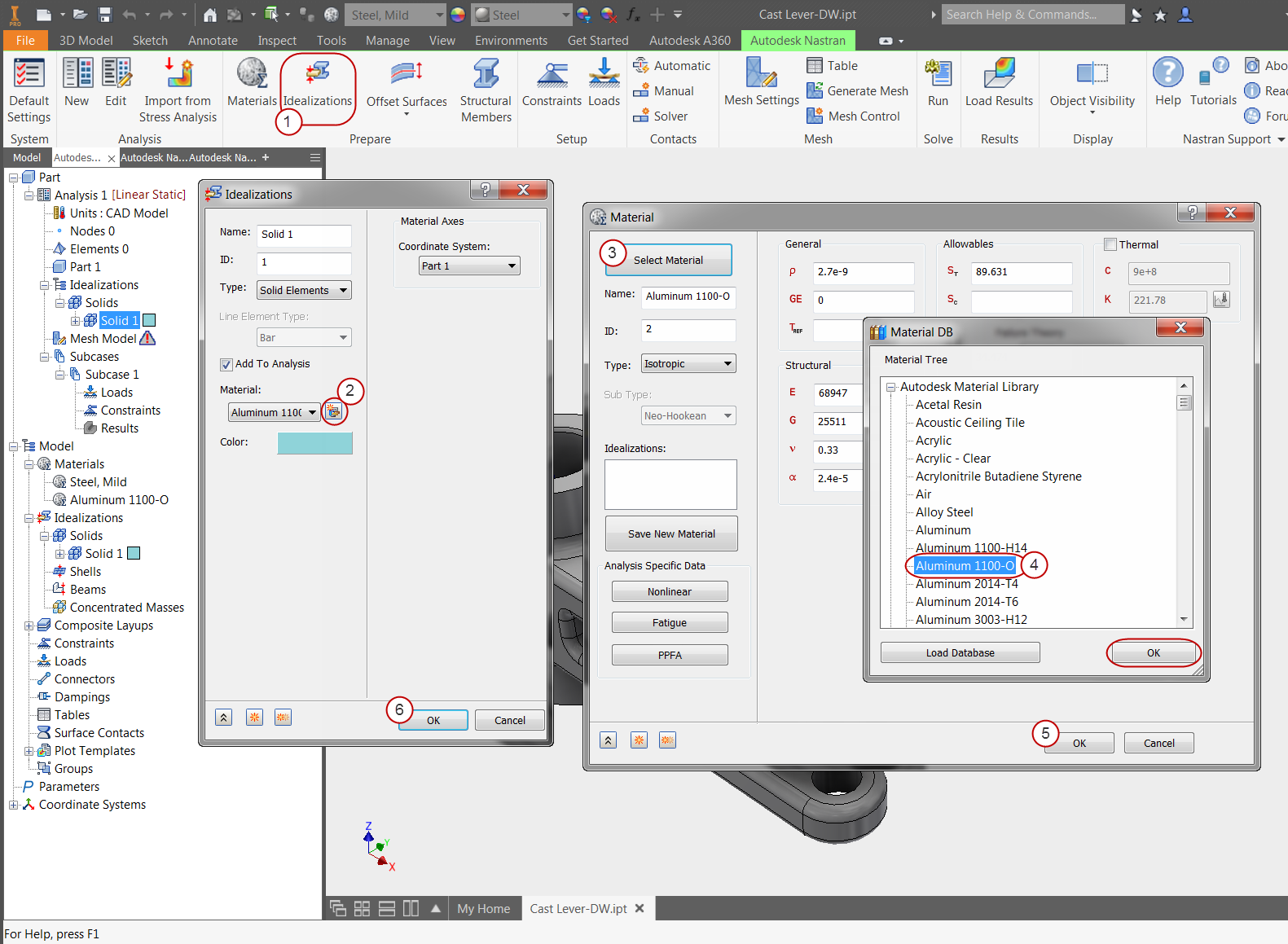
2. Define the Physical Property
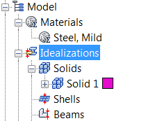
In the Model tree, expand the Idealizations node to check for any existing definitions, such as Solid 1. If any exist, right-click . Doing this ensures that you won't have unwanted materials appearing in the part mesh and the analysis.
- Click Idealizations on the ribbon.
- On the Idealizations dialog, click the New Material icon.
- On the Material dialog, click Select Material.
- On the Material DB dialog, expand the Autodesk Material Library list, and select Aluminum 1100-O from the list. Click OK.
- Click OK on the Material dialog.
- Click OK on the Idealizations dialog.
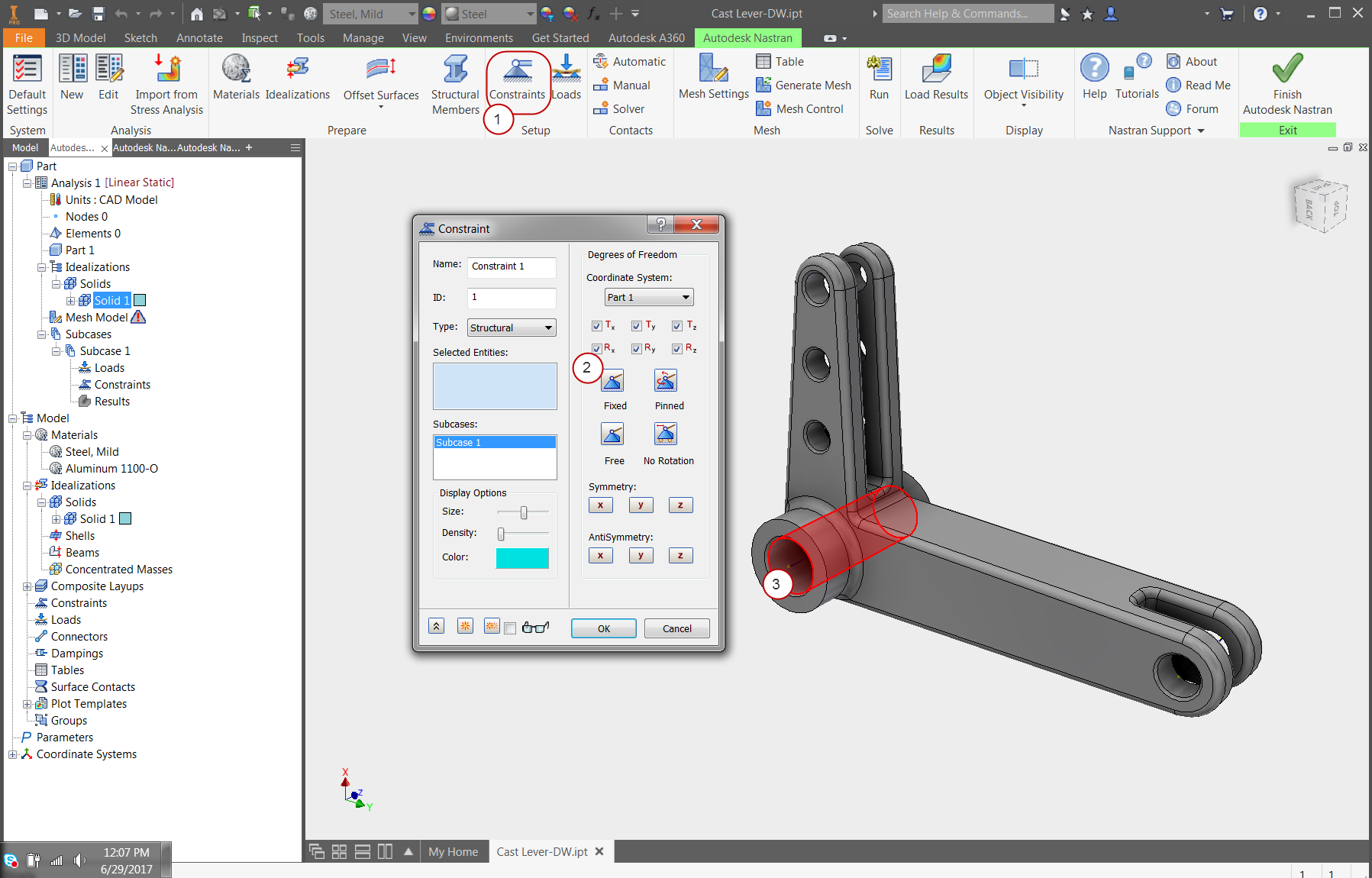
3. Constrain the Lever
- Click Constraints from the ribbon.
- Make sure the Fixed constraint is specified. (It is the default setting.)
- Select the inside surface of the center hole (as shown), and click OK.
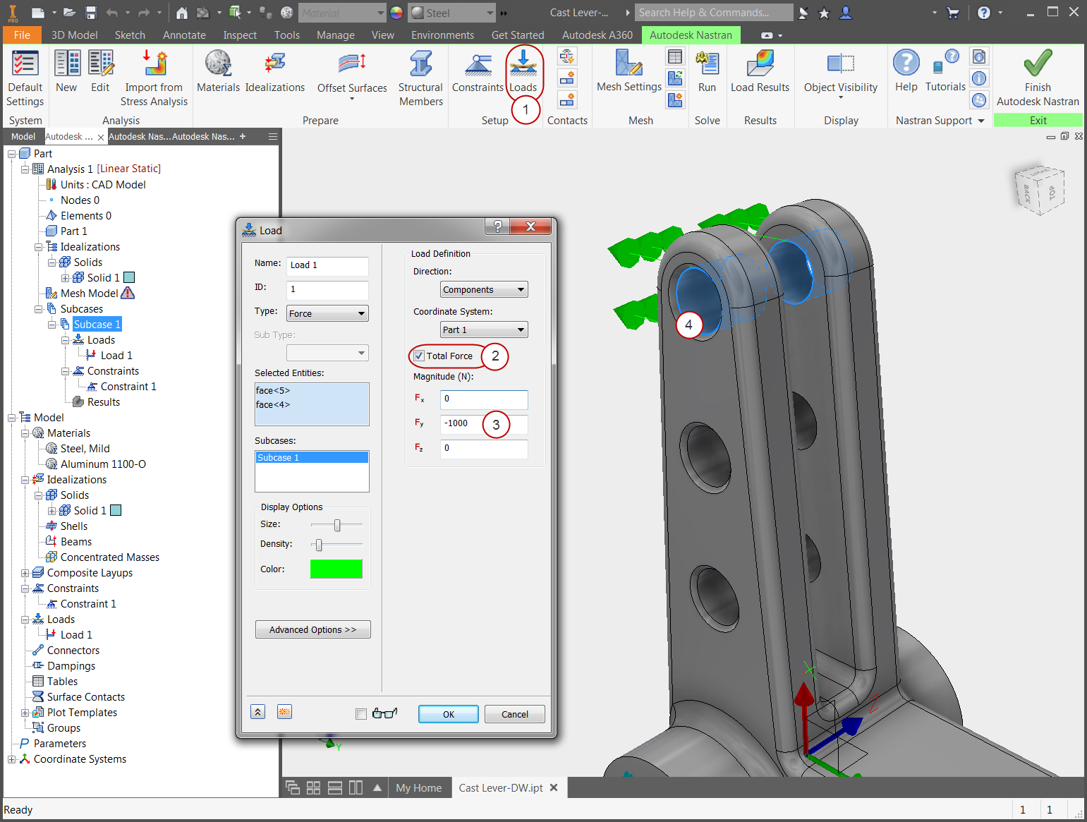
4. Define the First Load
- Click Loads from the ribbon.
- Select the inside surfaces of the two holes as shown.
- On the Load dialog, check the Total Force box.
- Enter a load of -1000 for Fy, and click OK.
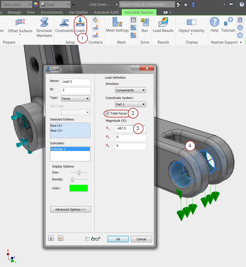
5. Define the Second Load
- Click Loads from the ribbon.
- Select the inside surfaces of the two bottom holes as shown.
- On the Load dialog, check the Total Force box.
- Enter a load of -687.5 for Fx, and click OK.
6. Mesh the Part and Run the Analysis
- Click Generate Mesh from the ribbon.
- After the mesh generates, click Run to start the analysis.
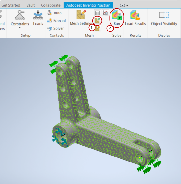
When the run is complete, click OK on the message box that indicates that the solution is complete.
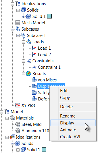
7. Review the Results
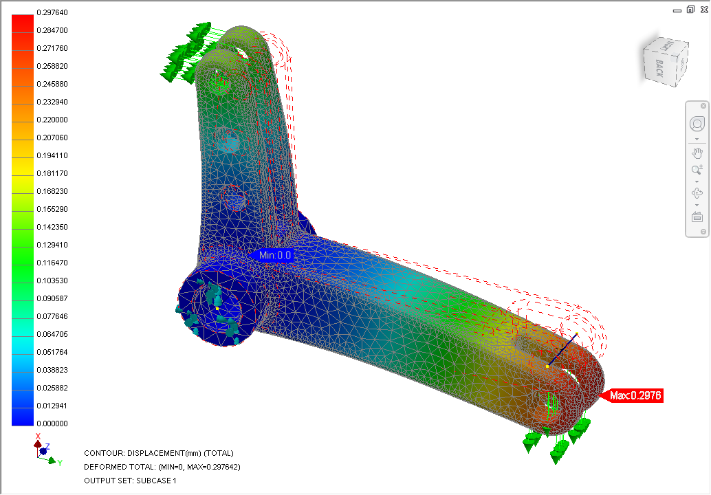
To plot displacement, right-click on Displacement from the tree, and click Display:
You should see this:
To animate the displacement, right-click on Displacement, and click Animate:
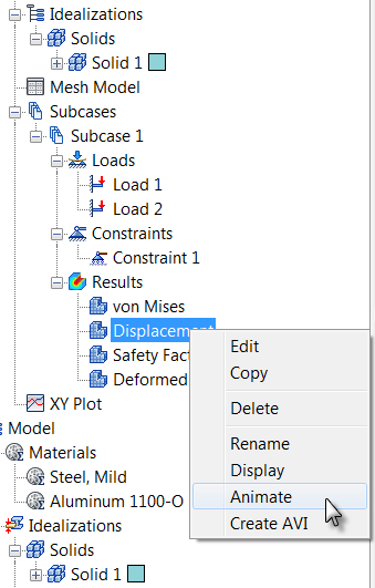
To stop animation, right-click on Displacement, and click Animate so that it is unchecked.
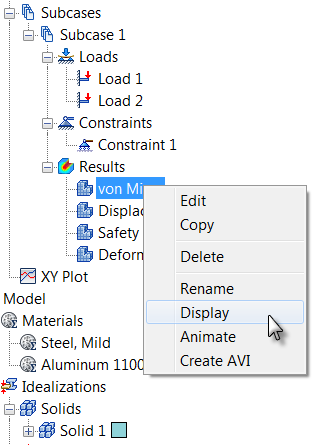
To plot von Mises stress, right-click .
To turn off the element edges, right-click , then in the Plot dialog, click the Visibility Options tab, and click the Element Edges slider to move it to the left.
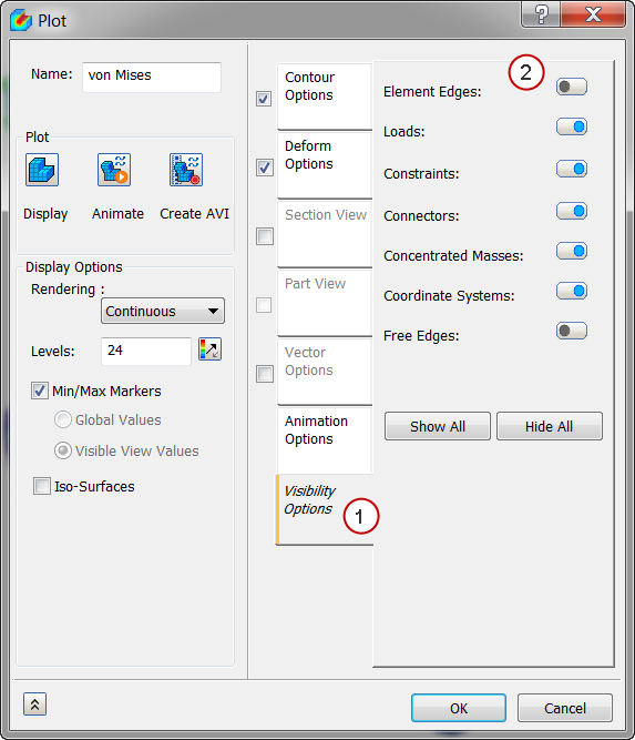
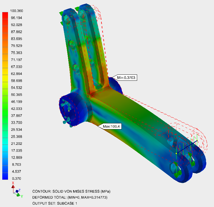
You should see this:
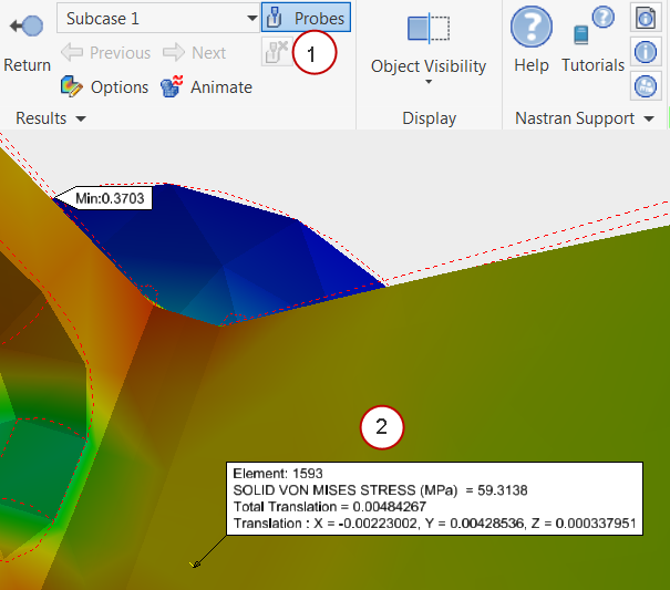
8. Probe for a Specific Value
- Click the Probes command from the ribbon.
- Hover over a location on the lever arm. The results are displayed:
Summary
In this exercise we computed the engineering values needed to properly load and constrain the cast lever. The steps we used were similar to those used in the first exercise (cantilever beam), but the model was a real-world part. We also learned how to extract results including the use of the Probe tool.
|
Previous Topic: The User Interface |
Next Topic: Modify Boundary Conditions Exercise |