- Right-click on
Subcases and select
New.
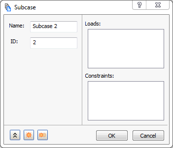
- Click OK to create a new blank subcase.
- In the tree view, right-click on Constraints and select New.
- Change the
Name to
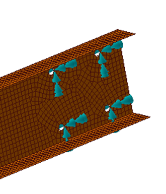
Fixed Holes and select the curves defining the holes at the right end of the beam.
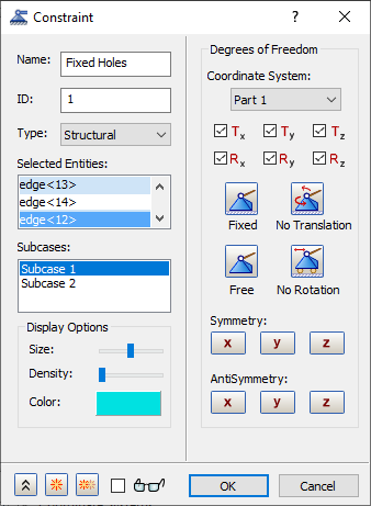
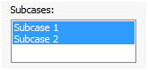
- Click both
Subcase 1 and
Subcase 2 from the
Subcases list. This will add this constraint to both subcases.
- Click on
 New button.
- Change the Name to Fix in Y Direction.
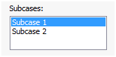
- Additionally, ensure that
Subcase 1 is selected in the
Subcases list.
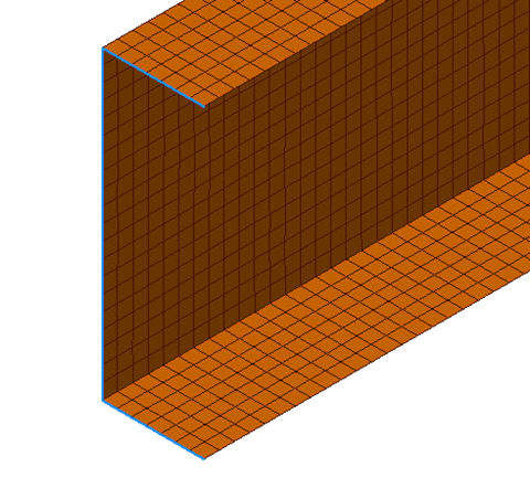
- Select the three edges of the beam opposite to the side with the holes.
- Click on
 Free button and select
Ty to fix the channel in the enforced Y direction.
Free button and select
Ty to fix the channel in the enforced Y direction.
- Click on
 Duplicate button. Notice that the selection of three edges of the beam opposite to the side with the holes is retained.
- Change the Name to Fix in X Direction.
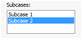
- Ensure that
Subcase 2 is selected in the
Subcases list.
- Click on
Free button and select
Tx to fix the channel in the enforced X direction.
- Click
OK.
 Constrain the same nodes/surfaces/curves in the direction of the enforced displacement/rotations. It is important that only the nodes that have the enforced displacement are constrained in the direction of the displacement. All other constraints will be treated as actual boundary conditions.
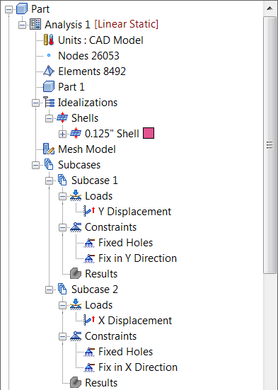
In the next steps we will apply loads.
- Right-click on Loads and select New.
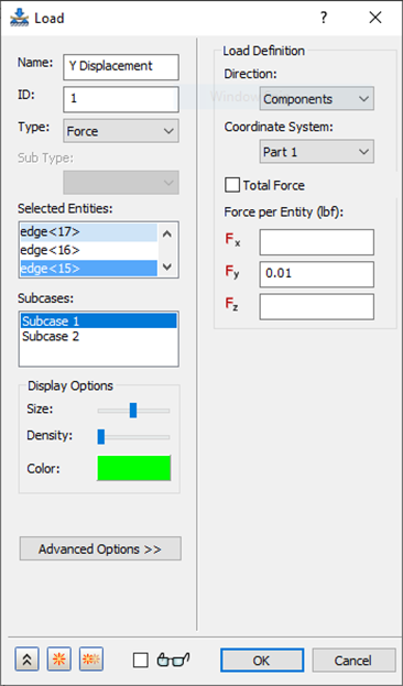
- Change the Name to Y Displacement.
- Change the Type drop-down to Enforced Motion and make sure Sub Type is set to Displacement.
- Additionally, ensure that
Subcase 1 is selected in the
Subcases list.
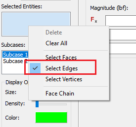
- Right-click inside the
Selected Entities box and check
Select Edges.
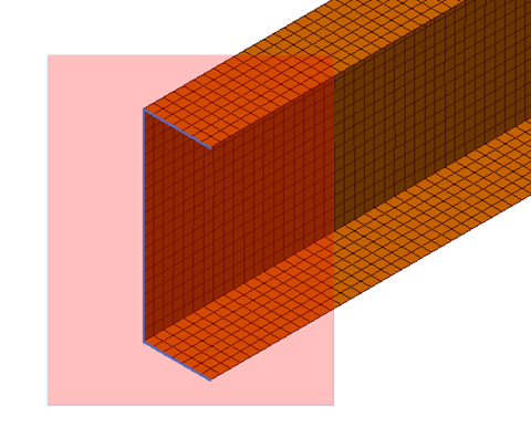
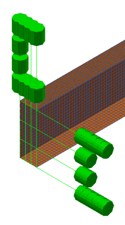
- Select the three edges of the beam opposite to the side with the holes by using box selection method. It will select only those edges.
- Under
Load Definition, enter
0.01 in the
Ty input box.
- Click the Duplicate button.
- Change the Name to X Displacement.
- Additionally, ensure that
Subcase 2 is selected in the
Subcases list.
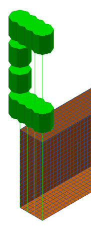
- The same three edges of the beam opposite to the side with the holes will be copied. The previous load will be shown and the load symbol (arrows) will display. Change the
Magnitude under
Load Definition, by entering
0.025 in the
Tx input box.
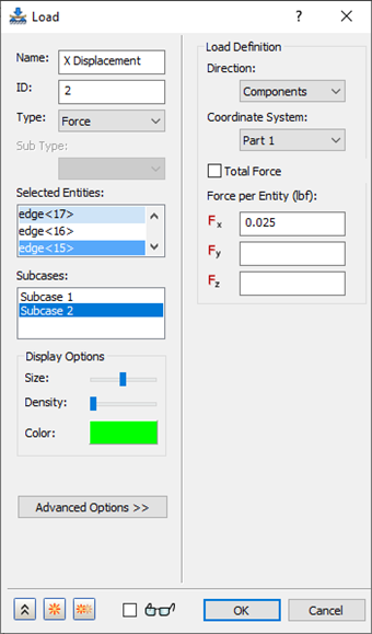
- Click
OK.