Apply the Constraints
- In the tree view, right-click on Constraints and choose New.
- Select the outer edges (not the entire surface) at the ends of the top tube and bottom tube.
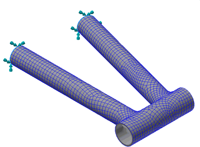
- Be sure that Subcase 1 is selected in the Subcases list.
- Leave all the defaults in the
Constraint dialog.
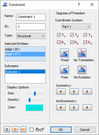
- Click OK to create the fixed constraint.
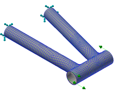
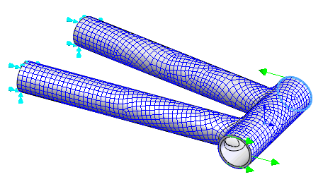
Apply the Loads
- Right-click on Loads and choose New.
- Select the edge at the top of the head tube, type
-100 in the
Fx field under
Magnitude. Be sure that
Subcase 1 is selected in the
Subcases list.
- Click on
 New button to create the second load.
- Select the edge at the bottom of the head tube, type
100 in the
Fx field under
Magnitude. Be sure that
Subcase 1 is selected in the
Subcases list, and then click
OK to create the load.
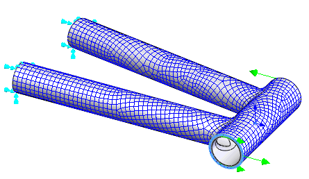
Define the Material Orientation
- At the top of the Part tree, right-click .
- Under Type select Surface V Direction.
- Select the five surfaces in the model. They should appear under
Oriented Geometry.
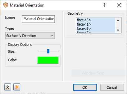
- Click
OK to create the material orientation. Notice the little green arrows that appear throughout the mesh. These identify the “0 angle” direction.