- In the tree view, right-click on Analysis 1 and click Edit.
- Input Bracket Analysis in the Name field and Modal Frequency Response in the Title field.
- Change the drop-down box for Type to Modal Frequency Response.
- Make sure that the
Output Controls are set as shown in the picture below.
Displacement and
Acceleration should be checked, while
Stress should be unchecked.
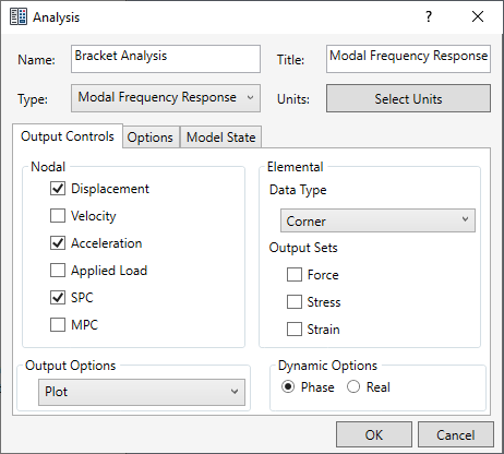
- Click OK.
 Dynamic analyses produce a lot of output and therefore, only output that is needed should be requested. It is quite easy for a result file to go well over the gigabyte size with dynamic analyses such as frequency response.
These settings are not critical to the analysis, but are measures to reduce the time of the analysis and produce only the output that the tutorial focuses on.
Define Material Properties
Create a new material by loading aluminum alloys from the material library.
- In the Model tree, right-click .
- In the dialog, click Select Material.
- The Material DB dialog will become populated with the available libraries. Click on Load Database.
- Browse to C:\Program Files\Autodesk\Inventor Nastran 2025\In-CAD\Materials and open the ADSK_materials.nasmat file. The material tree is populated with the available materials.
- Under the
Aluminum Alloys category, select
Aluminum 7075 Heat Treated (T6) Wrought.
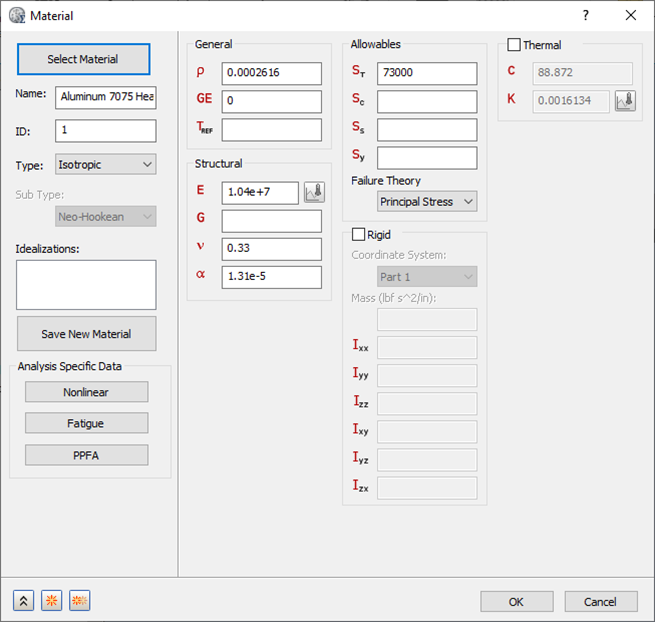
- Click Close and OK.
Define Element Properties
- In the
Model tree, under
Idealizations, check for any existing definitions under the standard categories, such as
Solids and
Shells. Solid 1, shown below, is an example of an existing definition:
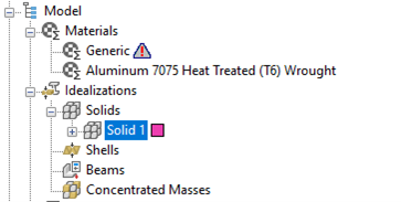
If there are any existing definitions, right-click . Doing this ensures that you won't have unwanted materials appearing in the part mesh and participating in the analysis.
- In the Model tree, right-click .
- Select
Solid Elements from the
Type drop-down menu.
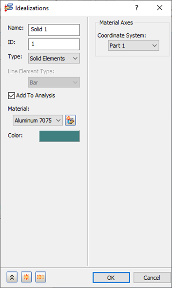
- Ensure that Material is set to Aluminum 7075 Heat Treated (T6) Wrought.
- Click OK.
Define the Mesh
- Right-click on Mesh Model and select Edit.
- Change the Element Size to 0.25.
- Make sure that
Element Order is set to
Parabolic.
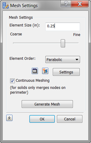 These settings will produce a “bad” mesh for a production run. This mesh is used as an example to demonstrate Modal Frequency Response. Normally, the mesh would be detailed.
- Click OK.