This tool allows you to define a local element size to selected vertices, edges, faces, or parts. Each mesh control you add is listed under
Mesh Model Mesh Control in the browser (model tree).
There are two ways to access the Mesh Control dialog:
- Click Mesh Control in the Mesh panel of the Inventor Nastran ribbon tab.
- Right-click Mesh Model in the browser and click Add Mesh Control.
Vertex Data
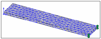
The following example illustrates the Vertex Data usage.
Default mesh:
- Right-click
Mesh Model and click
Add Mesh Control. The following dialog appears:
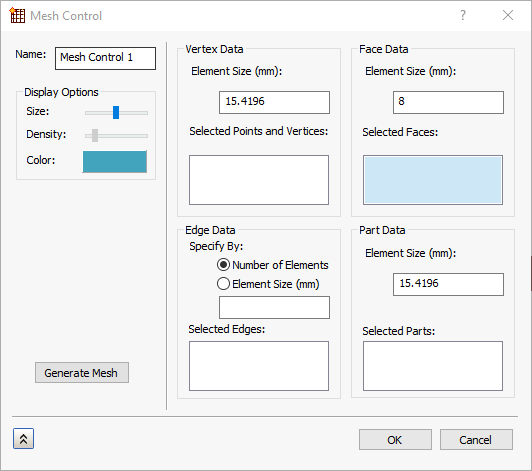
- Click in the Selected Points and Vertices box to make it active.
- Click each of the four vertices indicated with small green spheres in the above image of the default mesh. They are listed in the box.
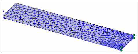
- Specify a local element size that is significantly smaller than the global size.
- Click OK.
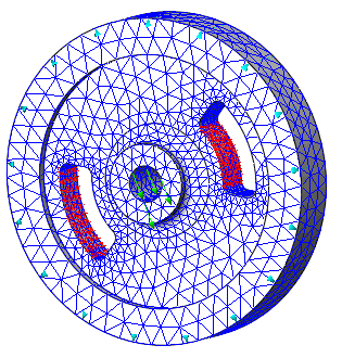
- Generate the mesh for the local size to take effect. The refined mesh looks as follows:
The entity selection and local mesh refinement techniques are similar for edges, faces, and parts, with one exception. You can specify edge refinement by element size or by number of divisions along the selected edges.
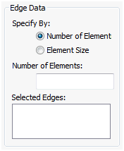
Edge Data
- In the
Specify By section, choose either
Number of Elements or
Element Size.
- If you choose
Number of Elements, you must enter the desired
Number of Elements along the
Selected Edges. The edge length is divided by the number of elements you specify, and the resulting elements are evenly spaced along the selected model edges when you generate the mesh.
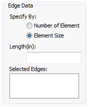
- If you choose
Element Size, you must enter a desired element
Length along the
Selected Edges. The program adjusts the element size as needed to produce a whole number of elements along the selected edges.
- If you choose
Number of Elements, you must enter the desired
Number of Elements along the
Selected Edges. The edge length is divided by the number of elements you specify, and the resulting elements are evenly spaced along the selected model edges when you generate the mesh.
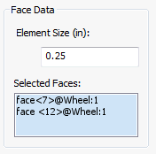
Face Data
- Specify the desired
Element Size for the
Selected Faces. The actual element size is adjusted by the mesher to produce a whole number of element faces along the selected model faces.
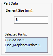
Part Data
- Specify the desired
Element Size for the
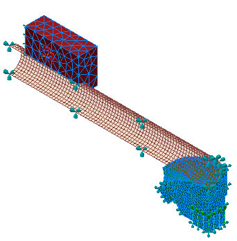
Selected Parts. The actual element size is adjusted by the mesher to produce a whole number of elements and to accommodate varying CAD feature sizes along the selected parts.
Display Options
Use the settings in the Display Options section to control the visual representation of the mesh controls you add.
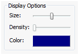
- Size: Change the size of the mesh control representation.
- Density: Control the density (number of) glyphs used to represent the mesh control.
- Color: Allows you to pick the color of the mesh control representation.
Generate Mesh
Click to generate mesh using the mesh control settings.
Miscellaneous
- In the
Mesh Control dialog there is a
New
 button, which accepts the current mesh control and clears the dialog for creating a new mesh control.
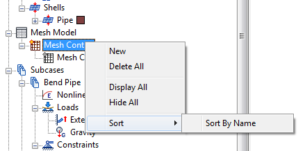
- Right-click
Mesh Controls in the browser to access a context menu with the following options: