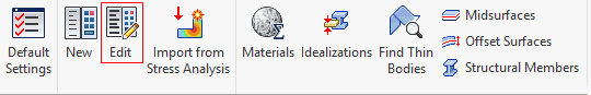
Click on the Edit button in the Analysis panel on the ribbon or right-click on Analysis at the top of the tree and select Edit to open the Analysis dialog.
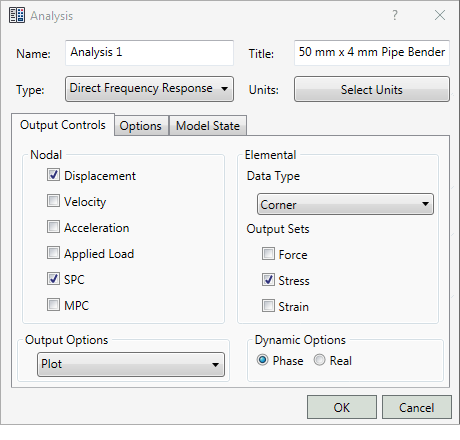
This will allow you to edit the features illustrated above (Name, Title, Type, Nodal and Elemental Output Control, Output Options, and Dynamic Options). Additional settings in the other dialog tabs (Options and Model State) are covered on this page as well. The exact options that appear depend upon the analysis Type that you choose.
- Name: The name that identifies the analysis in the model tree.
- Title: This title appears at the top of the analysis report.
- Type: Choose the desired analysis type from the drop-down menu.
- Select Units: Provides an option to define a unit system within the analysis dialog.

-
Unit System:
- CAD Model: It is the default unit system defined in Document Settings of the CAD Environment.
- SI: It is the MKS system (meters, kilograms, seconds, newton, kelvin and degree).
- Modified SI: It is the modified MKS system (millimeters, tonne, seconds, newton, kelvin and degree).
- English: It is the British / IPS unit system (inches, pounds seconds square per inch, seconds, pounds, Fahrenheit and degree).
- CGS: It is the system used to set the standard units as centimeter, grams, seconds, dyne, Celsius and degree.
- Output Controls tab (refer to the preceding image):
- Nodal : Allows you to request all the nodal results: Displacement, Applied Load, SPC, MPC, Grid Point Force Balance. For thermal analysis, you can request Temperature and SPC Heat Flow. Whereas for dynamic analysis, you can request Velocity and Acceleration.
- Elemental: Allows you to request Force, Stress, and Strain at the same time. For thermal analysis, you can request Heat Flux.
- Data Type: Choose whether to output data at the element corners or centroid.
- Output Sets: Allows you to request Force, Stress, and Strain at the same time. For thermal analysis, you can request Heat Flux.
- Output Options: Allows you to define Plot, Print, Punch, Punch and Plot.
- Plot: Results will be output only to the results neutral file.
- Print: Results will be output to both the model results output file and the results neutral file.
- Punch: Results will be output to the results neutral file, the model results output file, and the model results punch file.
- Punch and Plot: Results will be output to both the model results punch file and the results neutral file.
- Dynamic Options: Contains Phase and Real radio buttons. These buttons only appear when the analysis type is set to a Frequency and Random Response. It also contains PSD Output Control button, which will appear when the analysis type is set to Random Response.
- Options tab:
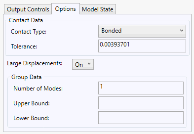
- Contact Data: Allows you to set the default settings for generating Automatic contacts.
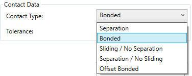
- Contact Type: Define automatic contacts between mating parts of the CAD Model. The available options are shown in the following image.
- Tolerance: It allows you to generate automatic contacts using the faces that are within the tolerance.
- Contact Type: Define automatic contacts between mating parts of the CAD Model. The available options are shown in the following image.
- Heartbeat: This option is only available for Explicit Analysis. It controls how often the analysis progress is written to the output file. The default Heartbeat interval is 50, so a line of text is written every 50 iterations.
- Large Displacements: This option is used in all Nonlinear analyses (Nonlinear Static, Nonlinear Buckling, Nonlinear Transient Response and Automated Impact Analysis (AIA)).
- ON: Large displacement and follower force effects and differential stiffness are included in the solution.
- OFF: Large displacement and follower force effects and differential stiffness are not included in the solution.
- Import Structural Model: This option is only available for Nonlinear Static analyses. When this option is enabled, you can browse for a structural input file (*.bdf or *.nas) that has been exported from
Advanced Material Exchange. The imported model can be run to simulate as-manufactured injection and compression-molded parts with
Helius PFA.
Note: In order to view the AME results, you must activate the centroidal result type if strain is selected as a result output.Refer to the Advanced Material Exchange User's Guide for more information about using Advanced Material Exchange.
- Group Data: Contains eigenvalue data for Linear and Nonlinear Buckling analyses.
- Contact Data: Allows you to set the default settings for generating Automatic contacts.
- Model State tab:
Autodesk Inventor Nastran supports Representations defined in Autodesk Inventor. This feature allows you to quickly hide/unhide or suppress/unsuppress parts of an assembly or subassembly.
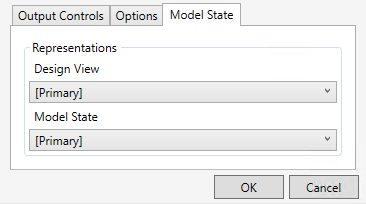
- Representations:
- Design View: This drop-down menu lists the Design View representations you created in Inventor. In these views, some assembly components are not visible, if they are not needed for a particular view and analysis. Hidden parts still participate in the analysis.
- Model State: This drop-down menu lists the Model States you created in Inventor. In these views, unwanted components are suppressed, or assembly parts are replaced with a single part representation. Suppressed parts do not participate in the analysis.
- Representations: