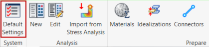
Click on the Default Settings button under the System panel on the ribbon.
Default Settings has the following options:
-
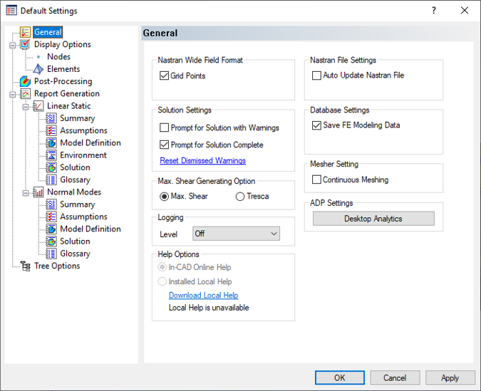
General - Allows users to set the Nastran field format, and various settings for the solution, logging, help, database, file, mesher, ADP, and technical preview.
- Nastran Wide Field Format: If Grid Points is checked, the Nastran deck will have the grid point entries in large field format (other Bulk Data entries will have this capability in future versions of Autodesk Inventor Nastran). Large field format can be used when small field format doesn’t provide enough significant digits.
- Solution Settings: If Prompt for Solution with Warnings is checked, Inventor Nastran will prompt the user if it should continue writing the .NAS file even when the solver encounters problems/errors with the model setup. If unchecked, the pre-processor will stop and terminate the creation of the Nastran Bulk Data file (*.NAS file) if problems in the model setup are found (i.e. linear static analysis with no load appearing in the first subcase). If Prompt for Solution Complete is checked, the user will see a dialog with a message that the solution is complete, and can click the dialog to display the solution. If unchecked, completed solution results appear directly, without displaying the dialog. Reset Dismissed Warnings will set all the dismissed warning messages to default.
- Max. Shear Generating Option: The user can select between
Max. Shear or
Tresca failure criterion.
If Tresca is selected, then Shell and Solid Tresca results are calculated and an output vector is created for the analysis that is completed. Tresca uses the equation: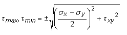
Where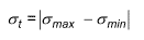
 and
and
 are the maximum and minimum principal stresses.
- Logging: This option is used for technical support of the software only. The setting should always be Off unless a support request is being submitted to Autodesk, Inc.
- Help Options: Use these options to switch between online Help and the optional local Help (if installed). A link is provided to Download Local Help, if desired.
- Inventor Nastran Online Help: Access the online Product Help documentation using your web browser and Internet connection.
- Installed Local Help: This option is only available if you download and install the optional local Help. When activated, Help files are accessed from your local hard drive and displayed in your web browser (no Internet connection required).
- Nastran File Settings: If Auto Update Nastran File is checked, the Nastran (.nas) file will continuously be updated. If checked, the user may notice performance delays while assembling the model. A Nastran file will always be generated when performing a Nastran solution, but this setting is primarily needed for running Nastran solutions from the Nastran File manual edit window.
- Database Settings: If Save FE Modeling Data is unchecked, the finite element model information (loads, constraints, mesh etc.) will not be saved to the CAD model file upon saving. This is one method to clear the Inventor Nastran information from a CAD model.
- Mesher Setting: Continuous Meshing of the model can be checked on or off. Currently, this feature is only available for shell elements.
- ADP Settings: Click Desktop Analytics to review or change your agreement to Autodesk's use of customer data for product improvement.
-
Display Options - Allows users to set global visualization of constraints, loads, max/min on contour, meshes, coordinate systems, material orientation, concentrated mass, connectors, free edges, mesh control etc.
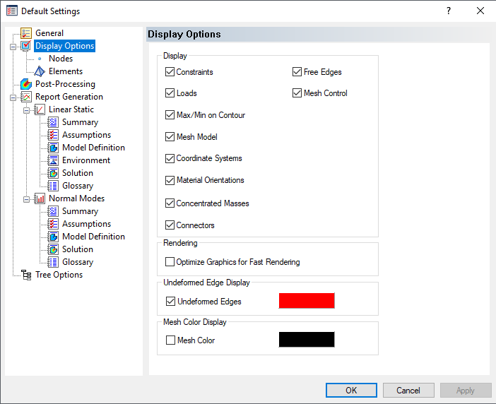
- Display: Free Edges will allow checking the continuous meshing between parts.
- Rendering: Will optimize the graphics for fast rendering loads and constraints.
- Undeformed Edge Display: Will display the undeformed edges when deformed plot is displayed.
- Mesh Color Display Sets the mesh color to black to be able to easier identify meshes.
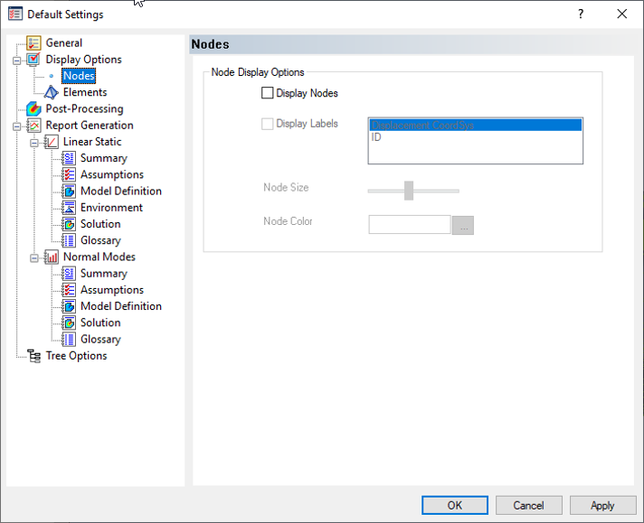
- Nodes: Defines settings for the visualization of nodes in the model. Users can choose to display nodes with either the displacement coordinate system or id tag. The size and color can also be changed.
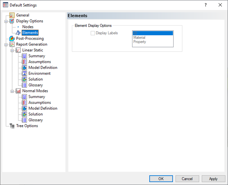
- Elements: Users can choose to display labels for elements in the model by ID, material, or property.
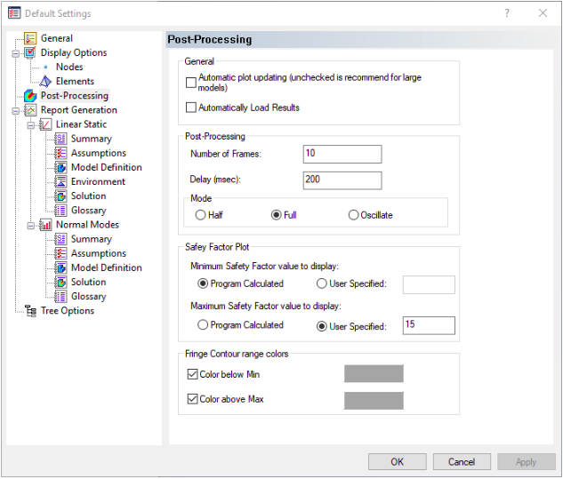
- Post-Processing - Allows users to set the default settings for post-processing options.
-
General section:
- Automatic plot updating: (Unchecked is recommend for large models.)
- Automatically load results: It allows you to load the results automatically when a model is opened.
- Post-Processing section: Allows you to set default settings for the following items:
- Number of Frames: Defines the number of frames in animations.
- Delay (msec): Specify the delay in milliseconds between animation frames.
- Mode Define the animation mode using one of the following three options:
- Half: Animation starts at the unloaded/undeformed state, gradually advances to the fully loaded/deformed results, and stops.
- Full: Animation starts at the unloaded/undeformed state, gradually advances to the fully loaded/deformed results, and then reverses (gradually returning to the unloaded/undeformed state).
- Oscillate: The first half of the animation is identical to the Full option. Then, a second full-cycle is added using a mirror image of the calculated deformed shape. This option is useful for visualizing vibration modes. For example, if the top of a tower bends to the right when determining the mode shape, it will also bend to the left for the second half of a full oscillation cycle.
- Safety Factor Plot section: Choose the desired default settings for Safety Factor plots.
- Minimum Safety Factor value to display: Choose whether to base the minimum value for Safety Factor plots on the Program Calculated minimum value (the default) or a User-Specified value.
- Maximum Safety Factor value to display: Choose whether to base the maximum value for Safety Factor plots on the Program Calculated maximum value or a User-Specified value. The default is a user-specified maximum value of 15. This option is useful because only relatively low safety factors are of interest, and the maximum safety factor in low-stress areas can be a very large number. The result is that one color can dominate the plot. Focusing on a small range of safety factor values produces a fuller spectrum of color and better resolution in the low safety factor regions.
- Fringe Contour range colors: Allow you to set colors above maximum and below minimum values for fringe contour plot. You can individually check/uncheck the boxes and select the color from the color pallet option.
-
General section:
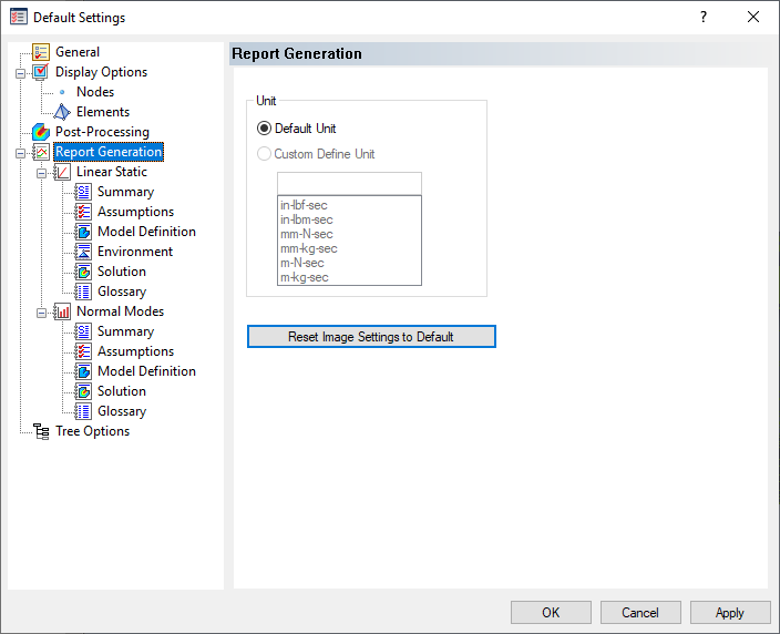
- Report Generation - Defines the settings for report generation and allows users to customize the text written to the report. Reports can only be made for Linear Static and Normal Modes solutions currently.
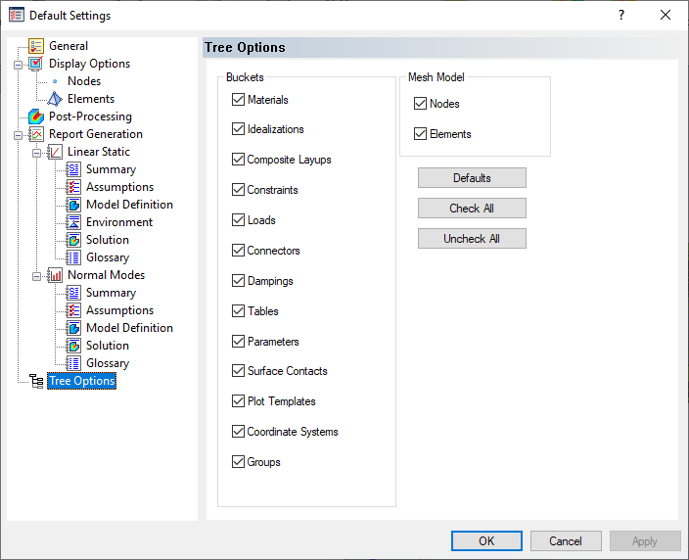
- Tree Options - Allows users to simplify the design tree by selecting and deselecting tree items that are not needed or desired.
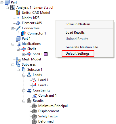
 The
Default Settings window can also be accessed by right-clicking an empty space of the Autodesk Nastran Model tree and selecting
Default Settings.
The
Default Settings window can also be accessed by right-clicking an empty space of the Autodesk Nastran Model tree and selecting
Default Settings.