Global Mesh Settings
There are two ways to edit the model mesh settings:
- Click
Mesh Settings in the
Mesh panel of the
Inventor Nastran ribbon tab.

- Right-click
Mesh Model in the browser (model tree) and select
Edit from the context menu (assuming that the
Switch To
 Mesh Setings option is activated).
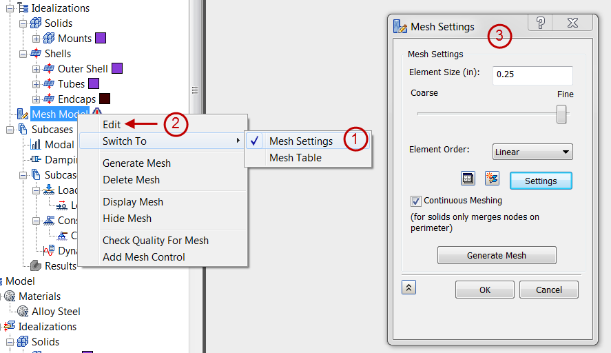
The Mesh Settings form in the figure below comes up, since this is the default selection for the Edit command.
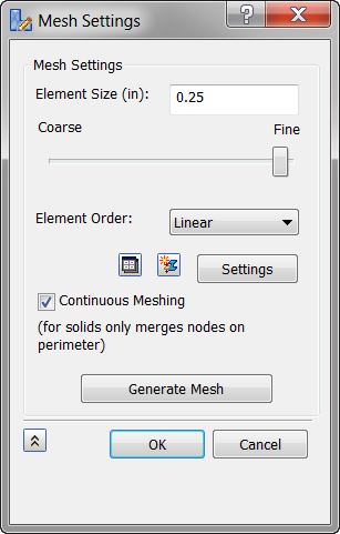
- Element Size: Global element size of the model. This field initially has a default size that you can change by entering a numeric value or using the Coarse to Fine slider below.
- Element Order: Parabolic or linear elements.
- Mesh Table (
 ): This icon allows you to switch from the global
Mesh Settings to the
Mesh Table.
): This icon allows you to switch from the global
Mesh Settings to the
Mesh Table.
- New Idealization (
 ): This icon allows you to create a new Idealization.
- Settings: This button allows you to define more
Advanced Mesh Settings, as shown below.
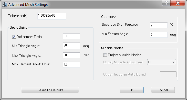
- Tolerance: Adjusting this mesh tolerance value will help you mesh parts that otherwise fail to mesh.
-
Basic Sizing:
- Refinement Ratio: Changes the mesh size to create more uniformity. Mesh element size deforms along with edges, curves, holes, bumps, etc. The larger the refinement ratio, the larger the mesh size.
- Min Triangle Angle: The minimum angle allowed at the vertex between any two edges in the mesh.
- Max Triangle Angle: The maximum angle allowed at the vertex between any two edges in the mesh. As max angle increases, a more uniform distribution of meshing is produced.
- Max Element Growth Rate: As growth factor increases, mesh element size increases. The smaller mesh elements become more and more concentrated to the entity (holes, bumps, etc) as growth factor increases.
-
Geometry:
- Suppress Short Features: Suppresses or covers up small features, such as holes, bumps, etc.
- Min Feature Angle: Controls the angle of mesh elements around different features such as edges, holes, bumps, etc.
-
Midside Nodes:
- Project Midside Nodes: Adds midside nodes to meshes. Elements along curves and edges are affected. If turned off, full mesh lines may not be completely visible.
- Quality Midside Adjustment: Controls midside adjustment and adjusts mesh if necessary.
- Upper Jacobian Ratio Bound: Ratio that governs quality midside adjustment.
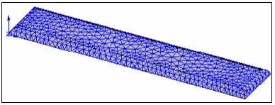
The following figures illustrate some mesh types.
Combined plane mesh with Quadrilaterals and Triangles:
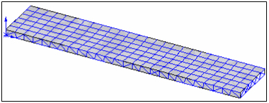
Solid mesh:
- Continuous Meshing: This checkbox will enable continuous meshing in the case of Shell elements, and it will merge the nodes within the tolerance specified for Solid elements.
- Generate Mesh button meshes the part or assembly.
Mesh Table
You can access the Mesh Table to define mesh settings on a per-part basis in two ways:
- Right-click
Mesh Model in the browser and activate the
Mesh Model Switch To Mesh Table option. Then, right-click
Model Mesh again and choose
Edit from the context menu.
- Click
Table in the
Mesh panel of the
Inventor Nastran ribbon tab.

The following dialog appears:
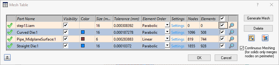
- The checkmark icon (
 ) shows that a particular part is meshed.
- Part Name: Provides the information of parts added in the Mesh Table.
- Visibility: Checkbox that allows you to switch the mesh visibility ON and OFF for the respective part.
- Color: Shows the physical property color assigned for the particular part as mesh.
- Size: Global element size of the model. This field initially has a default size that changes based on the model's dimensions.
- Element Order: Parabolic or linear elements.
- Settings: Allows you to define more advanced mesh settings, as described above, under the Global Mesh section.
- Nodes and Elements: It gives the number of nodes and elements in the respective part mesh.
 : The checkbox column selects all or individual parts for editing. You can toggle the state of the checkboxes for individual parts, or click the checkbox in the header to toggle the select or deselect all parts in a single click. The following actions are applicable when one or more boxes are checked:
- The
 and
and
 buttons are available. Clicking these buttons will generate the mesh or delete the mesh, respectively, for the selected parts.
- If two or more parts are checked, editing a setting (Visibility, Color, Size, Tolerance, or Element Order) causes the new value or state to be applied to all checked parts in a single operation. However, the advanced settings cannot be edited for multiple parts. The boxes must be unchecked to click Settings and access the Advanced Mesh Settings dialog.
- The
- Zoom (
 ): Click this icon to zoom the model viewpoint into that particular part.
- Mesh Settings (
 ): Click this icon to switch from the
Mesh Table to the global
Mesh Settings.
): Click this icon to switch from the
Mesh Table to the global
Mesh Settings.
- New Idealization (): This button allows you to create a new idealization.
- Continuous Meshing: This checkbox will enable the continuous meshing in case of Shell elements and it will merge the nodes within the tolerance specified for Solid elements.