Degrees of freedom (DOF) are the most basic variables solved for in finite element analysis. Each element group has different degrees of freedom.
A degree of freedom corresponds to a translation or a rotation at each node of an element. There can be up to 6 degrees of freedom per node depending on the element type.
- 1 direction translation (often X translation)
- 2 direction translation (often Y translation)
- 3 direction translation (often Z translation)
- 4 direction rotation (often X rotation)
- 5 direction rotation (often Y rotation)
- 6 direction rotation (often Z rotation)
In reference to cylindrical coordinate system the degrees of freedom would correspond as follows:
- Degree of freedom 1 corresponds to translation along the r direction
- Degree of freedom 2 corresponds to translation along the θ direction
- Degree of freedom 3 corresponds to translation along the z direction
- Degree of freedom 4 corresponds to rotation about the r direction
- Degree of freedom 5 corresponds to rotation about the θ direction
- Degree of freedom 6 corresponds to rotation about the z direction
This is why degrees of freedom are often described in terms of number 1,2,3,4 etc.
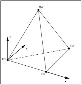
Solid elements have 3 degrees of freedom per node. Solids only support translational (DOFs) at each node. Therefore, moments cannot be applied to solids directly. A moment acts on the rotational degrees of freedom.
Each grid (G1-G4) in the image shown below can only translate. This is the formulation for the solid elements in Autodesk Nastran solver.
Shell elements have 5 degrees of freedom per node with quasi 6th degree of freedom.
Line elements (in this software) have 6 degrees of freedom per node.
Rotations, displacements, and temperatures are solved for at the nodes. Some elements have the capability of more nodes per element increasing the order of interpolation. The default configuration for solid elements is parabolic, but has a linear order option. The default configuration for shell elements is linear, but has a parabolic option. The default for line elements is linear and does not have an alternate configuration.
To calculate elemental quantities, the solver integrates over the volume of the element using specified points called Gauss points, and hence Gaussian quadrature is used to carry out this integration. By increasing the element order (choosing parabolic versus linear) the solver increases the number of Gaussian points used in the process.