Orientation in a 3D Workspace
Although Autodesk Navisworks uses the X, Y, Z coordinate system, there is no hard-and-fast rule as to which way each of these particular axes actually “points”.
Autodesk Navisworks reads the data necessary to map which way is “up” and which way is “north” directly from the files loaded into your scene. If this is not possible, by default, Z is treated as “up” and Y is treated as “north”.
It is possible to change the “up” and “north” directions for the entire model (world orientation), and the “up” direction for the current viewpoint (viewpoint up vector).
Align the Viewpoint Up Vector to the Current View
- In Scene View, right-click to open the context menu.
- Click Viewpoint > Set Viewpoint Up > Set Up.
Align the Viewpoint Up Vector to One of the Preset Axes
In Scene View, right-click to open the context menu.
Click Viewpoint > Set Viewpoint Up.
Click one of the preset axis. Choose from:
- Set Up + X
- Set Up - X
- Set Up + Y
- Set Up - Y
- Set Up + Z
- Set Up - Z
Change the World Orientation
Click Home tab > Project panel > File Options
 .
.In the File Options dialog box > Orientation tab, enter the required values to adjust the model orientation.
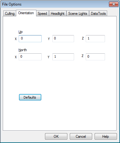
Click OK.