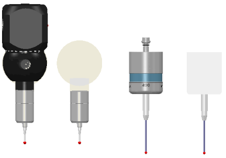
Select Home tab > Probe Path > Verify to check probe paths for:
- Out-of-bounds (outside of machine boundary) moves
- Collisions between the probe and the part
- Missing contact
moves
Missing contact faults are reported when a contact point is not found during a measure move. When not using a model for the inspection, you can disable this check by selecting the Ignore missing contact points check box in the Probe Path Verification page of the Options dialog.
- Illegal contact moves
PowerInspect displays icons in the inspection sequence to warn of potential problems for inspection sequence items that have probe paths.
Verify may not detect all probe path errors and potential collisions. You should check the inspection sequence before running a live inspection. For example, probe changes and probe-orientation changes are not verified, and are displayed in light grey:
Simulating inspections
When Verify is selected, PowerInspect checks for collisions between the part and all movable parts of the measuring device during interactive simulations. If a collision is detected, the simulation pauses and an error is displayed. Click:
- Ignore to ignore the current error but continue to display warnings if other collisions are detected.
- Ignore All to ignore all errors in the current simulation.
- Stop to stop the simulation.
PowerInspect identifies the parts of the probe body that are used for verification by displaying a transparent envelope in the CAD view. Press the F10 key to show or hide the envelope, for example:
