PLP alignments enable you to align the part to the CAD model using a plane, line and point for which you know the nominal coordinates. You do not need to use or create geometric items to measure the alignment, but the features you use must lock all six degrees of freedom. For example, the:
- plane specifies the Z coordinate, and locks rotation around the X and Y axes and translation in the Z axis.
- line locks rotation around the Z axis.
- point locks translation in the X and Y axes.
To create a PLP alignment:
- Select the Definition level in the inspection sequence.
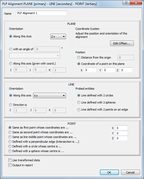
- Click Alignments & Datums tab > Alignments panel > PLP. The
PLP Alignment dialog is displayed.
- Enter a Name for the alignment.
- Specify an
Orientation to determine the normal vector of the plane. Select:
- Along this axis to choose the axis from the list. For example, if the direction in which the plane is to be probed is Z+ in the CAD datum, specify Z+ in the Along this axis box. This is independent of the orientation of the part on the measuring device.
- With an angle of to specify a plane at an angle to a selected plane. Select the plane and rotation axis from the list, and enter the angle.
- Along this axis (given with coord) to enter the vector in the I, J, K boxes.
In each case, the positive side of the plane is the same as the clearance probing direction.
- To apply an offset to the alignment, click Edit Offset and enter the offset in the Transformation Matrix dialog.
- Specify the
Position of the plane to lock its translation. Select:
- Distance from the origin to specify the distance of the coordinate system from the origin. The positive direction is determined by the plane's normal vector.
- Coordinate of a point on this plane to specify the coordinate of a point that lies in the plane.
If you select this option, you do not have to enter the coordinate specified by the plane. For example, if the plane's orientation is defined as X+, type the Y and Z values for the point, and leave the X value as 0.
- Choose an
Orientation option to specify the direction of the line. Select:
- Along this axis to orientate the line from the first point to the second point.
- Direction is to enter the vector in the I, J, K boxes.
- Choose a
Probed entities option to specify how the line is created. Select:
- Line defined with 2 circles to create a line between the centres of two probed circles.
- Line defined with 2 spheres to create a line between the centres of two probed spheres.
- Line defined with 2 points on an edge to probe a line along an edge.
- Choose an option to specify the point. Select:
- Same as first point whose coordinates are to use the centre of the line's first circle (or sphere).
- Same as second point whose coordinates are to use the centre of the line's second circle (or sphere).
- Same as line middle point whose coordinates are to use the mid-point of the line.
- Defined with a perpendicular edge (whose intersection is) to use the intersection of the line with another probed line.
- Defined with a circle whose centre is to use the centre of a probed circle.
- Defined with a sphere whose centre is to use the centre of a probed sphere.
The Same as options are available only when you select Line defined with 2 circles or Line defined with 2 spheres as the Probed entities option.
- Type the coordinates of the point in the
X,
Y, and
Z boxes. The point is projected onto the reference plane.
You do not need to enter the coordinate of the plane on which the point is projected. For example, if the plane is defined at Z+, [0, 0 100], enter the point's X and Y coordinates and leave the Z coordinate as 0.
- If the inspection sequence contains constructed features that use measurements taken by different measuring devices or from different device positions, select the
Use transformed data check box. This converts the device coordinates to CAD coordinates so that all calculations use a common reference system.
The check box has no effect when all coordinates in the inspection are collected with one measuring device in one position, or when the inspection sequence contains no constructed features.
- Click OK to close the dialog and measure the alignment.