The Geometric Multi-Measure dialog enables you to probe multiple features on a part and automatically create sequence items from the measurements.
To manually identify probed features
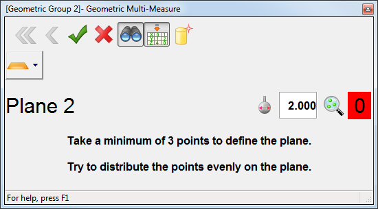
- Open a Geometric group, and click Measure tab > Manual panel > Multi-Measure. The CAD view is shown in full screen mode and the Geometric Multi-Measure dialog is displayed.
- If you want to display the coordinates and deviation of the points as you probe them, click
 .
.
- Select the
Auto-extract nominals from CAD
 button to load the nominals into each item you create.
PowerInspect automatically enables the items'
Use nominals option so it can report whether the items are in- or out-of-tolerance.
button to load the nominals into each item you create.
PowerInspect automatically enables the items'
Use nominals option so it can report whether the items are in- or out-of-tolerance.
To select the Auto-extract nominals from CAD button by default, select the Enable by default check box in the Auto nominals from CAD page of the Options dialog.
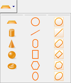
- Click the item selection button and choose the type of item you want to probe.
- To measure
3D features, follow the instructions in the dialog, then click
 to save the points.
- To measure
2D features with separate reference planes:
- Select the plane on which you want to project the 2D item in the Reference Plane list.
- If you want to specify the position of the feature relative to the reference plane, enter the feature's average height in the Offset/Thickness box.
- If you want PowerInspect to calculate the average height from the measurement, select the Calculate from measurement check box.
- Follow the dialog instructions to probe the feature, then click
to complete the measurement.
- To measure
Compound items:
- Follow the dialog instructions to probe the reference plane, then click
to save the points.
- Follow the instructions to probe the feature, then click
to complete the measurement.
A red background on the point counter indicates you have not yet probed the minimum number of points required to calculate the feature's dimensions; a green background indicates the dimensions can be calculated.
- Follow the dialog instructions to probe the reference plane, then click
- When you have finished, click
 to close the dialog. The items created for the features you measured are listed in the inspection sequence.
To auto-detect probed features
- Create and measure an alignment.
- Open a geometric group, and click Measure tab > Manual panel > Multi Measure.
The CAD view is shown in full screen mode and the Geometric Multi-Measure dialog is displayed.
- If you want to display the coordinates and deviation of the points as you probe them, click
.
- Select the
Auto-extract nominals from CAD
button, and then select the
Auto-detect item type
 button.
- Probe the feature on the part.
PowerInspect compares the points to the model and chooses the feature with the closest matching nominals. As you probe more points, the feature can change. If PowerInspect chooses the wrong type of feature, select Auto-detect item type, and then select the correct feature type from the palette.
You can adjust the sensitivity of the auto-detection feature using the Search distance option on the Auto nominals from CAD page of the Options dialog.
- If you are probing a 2D feature, such as a circle:
- Select the plane on which you want to project the 2D item in the Reference Plane list.
- If you want to specify the position of the feature relative to the reference plane, enter the feature's average height in the Offset/Thickness box.
- If you want PowerInspect to calculate the average height, select the Calculate from measurement check box.
- When you have finished probing the feature, click
to save the points.
- When you have finished, click
to close the dialog. The items created for the features you measured are listed in the inspection sequence. To display the measurements, select the
Results
tab.