Use material condition modifiers in GD&T measurements to specify how the tolerance zone is affected by other tolerances that apply to a feature or datum feature. For example, when a feature is designed to be fitted with another feature, such as a pin or a hole, the tolerances for the size and position affect the result.
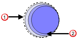
The following example shows the relationship between the tolerances for the position  and size
  of a pin:
The way in which the final tolerance is calculated depends on the modifier you select:
- RFS (Regardless of Feature Size) or RMB (Regardless of Material Boundary) — This is the default modifier, which restricts the tolerance to exactly the one specified. This does not have a GD&T symbol.
- MMC (Maximum Material Condition) or MMB (Maximum Material Boundary) — Specifies the maximum material condition of the actual mating size of the feature. For holes, this means the smallest the hole can be for the corresponding pin to fit. For pins, or other features that extrude from a part, this means the largest the feature can be to fit into the corresponding hole.
If a tolerance is followed by
 , it applies when the feature is at the worst condition of fit. As a feature departs from MMC or MMB, it moves away from the worst case. This allows tolerances on other dimensions to be increased by the feature's distance from MMC or MMB.
 - LMC (Least Material Condition) or LMB (Least Material Boundary) — Specifies the minimum material condition of the actual mating size of the feature. This is useful where a minimum material thickness is important, such as holes near the edge of a part, or holes in bosses.
If a tolerance is followed by
 , it applies when the feature is at the worst condition of fit. As a feature departs from LMC or LMB, it moves away from the worst case. This allows tolerances on other dimensions to be increased by the feature's distance from LMC or LMB.
When you select a maximum or least material modifier, PowerInspect uses a bonus to increase the tolerance, depending on the feature's accuracy. The way in which the bonus is calculated depends on the type of feature being measured, and the difference between its measured and nominal values:
|
Type of feature |
Material modifier |
Bonus |
|
Hole For example, a cylinder |
MMC or MMB |
Measured diameter - (Nominal value - Lower tolerance) |
|
Hole For example, a cylinder |
LMC or LMB |
(Nominal value + Upper tolerance) - Measured diameter |
|
Boss For example, a cylinder |
MMC or MMB |
(Nominal value + Upper tolerance) - Measured diameter |
|
Boss For example, a cylinder |
LMC or LMB |
Measured diameter - (Nominal value - Lower tolerance) |