Use digitised curves to probe a curve across the surfaces of a part. Use them to measure sections around a part and to build up a picture of a part for reverse engineering.
Where a point is added to the curve is determined by its proximity to the nearest segment.
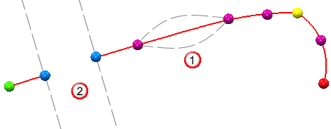
If the new point is:
- Within the catchment zone of a link segment
 , it is inserted between the existing points.
- Within the catchment zone of a gap segment
 , a link segment is added between the new point and the nearer existing point, and a gap segment is inserted between the new point and the further existing point.
- Outside the catchment zone of a segment, it is appended to the start or the end of the curve, whichever is nearer.
The Polyline option controls whether the digitised curve is a polyline or spline.
If the digitised curve is a spline, Spline Tolerance specifies the maximum distance that the spline curve can vary from the measured position of the probed points. A higher value creates a smoother curve through an averaged path of points. The curve masks flaws in the surface, but may not touch all the points. A lower value creates a curve that follows the points more closely and gives a more accurate representation of the surface. A Spline Tolerance of 0 forces the curve to pass through all the probed points.
Curve-point colours
As you probe a digitised curve, PowerInspect uses colour to indicate the type of each point it contains. You can change the curve colours using the Colours > Curves page of the Options dialog. By default:
- Green indicates the first point of the curve.
- Red indicates the last point of the curve.
- Blue indicates a gap point.
- Yellow indicates an edge point.
- Purple indicates other points in the curve.
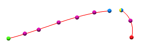
Points that fall into more than one category are multi-coloured. For example, an edge point that is also marked as a gap point is shown as a blue and yellow sphere: