You can place Probe & Parameters items in the Definition level of the inspection sequence or within a geometric group. This enables you to specify and change the probe tool and probing parameters for individual items as well as ranges of items or the entire sequence.
The following example demonstrates how Probe & Parameters items are used in an OMV inspection:
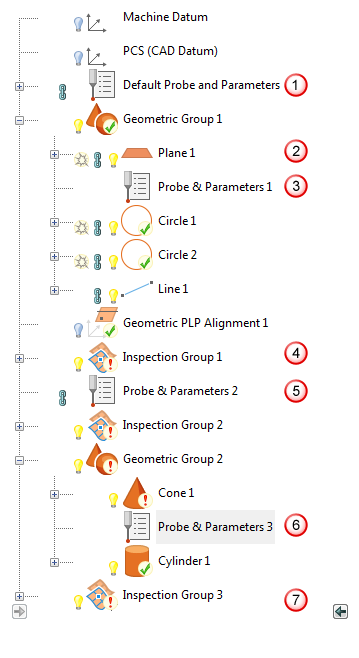
 PowerInspect automatically adds a Probe and Parameters item when you create a document. Use it to specify the initial probe and probing settings for the inspection.
 Plane 1 uses the settings specified by the Default Probe and Parameters item.
 Probe and Parameters 1 switches to a smaller probe for the holes used to create the alignment.
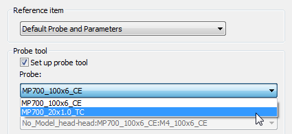
Only the probe is changed by this item so the other parameter values are inherited from the reference item. Because the group contains no other Probe and Parameters items, its settings are used for the remaining features in the group.
 Because Probe and Parameters items apply only to the group in which they are included, Inspection Group 1 automatically reverts to the settings specified by the preceding item in the Definition level of the sequence (in this case, the Default Probe and Parameters item).
The setting changes are sent to the measuring device as part of the probe path created for Inspection Group 1; not by the alignment item. This is because probe and parameter settings are updated only by items that create a probe path.
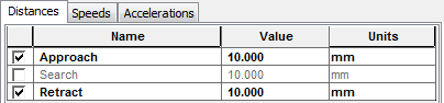
 To avoid collisions, Probe and Parameters 2 increases the approach and retract distances to 10 mm for Inspection Group 2.
 Probe and Parameters 3 sets Probe and Parameters 1 as its reference item without making any other changes.
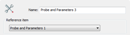
This forces Geometric Group 2 to use the same settings as Geometric Group 1 without re-entering the first group's settings. It also ensures that any future changes to Probe and Parameters 1 are automatically reflected in Geometric Group 2.
 Inspection Group 3 reverts to using the settings specified in Probe and Parameters 2. If you want to revert to the settings specified at the beginning of the sequence, you can insert another Probe and Parameters item that references the Default item.