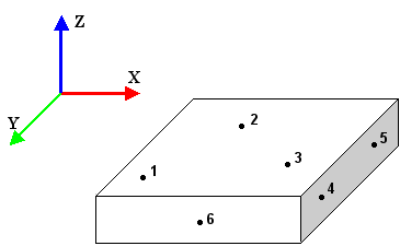
Measure six points on three surfaces: three points to define a plane, two points to define an axis, and one point to define a position.
For example:
This 3-2-1 rule fixes the part in 3D space and enables PowerInspect to calculate a transformation that converts PCS coordinates to Machine coordinates.
To create an initial alignment:
- Connect PowerInspect to the measuring device.
- Double-click PCS (CAD Datum) in the inspection sequence.
- In the Transformation Matrix dialog, click the
3-2-1
button.
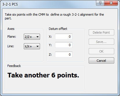
- In the Plane list, select the axis to be defined by the probed plane.
- In the Line list, select the axis to be defined by the probed line.
- To offset the datum, enter the X, Y, and Z values of the offset in the Datum offset area.
- Take six points on the part using the 3-2-1 rule:
- Points 1, 2, and 3 specify a plane. This locks two rotation and one translation axis.
- Points 4 and 5 specify a line. This locks one rotation and one translation axis, and the order of the points specifies the direction of the line.
- Point 6 specifies a second line that is orthogonal to the plane axis and the line created by points 4 and 5. This locks the remaining translation axis, and the intersection point between the two lines gives the position of the origin.
To delete the last point taken, click Delete Point.
As you take each point, the Feedback area displays the number of points remaining. When all six points are taken, the area displays: Six points received. Matrix updated to indicate that the initial alignment has been created.
- To save details of this alignment to a matrix (.mat) file for future use, click Save and specify the name of the file.
- Click OK to close the dialog and save your changes.
To display the transformation, right-click the PCS (CAD datum) in the inspection sequence and select Edit Initial Alignment from the context menu.