Use hem-edge points to measure a rounded edge on a part.
Note: On-the-fly Edge groups are available only when creating inspections for CNC and Manual machines.
To measure a hem edge:
- Create an On-the-Fly Edge Group, and open the inspection group dialog.
- Enter a Name and Coordinate system for the group.
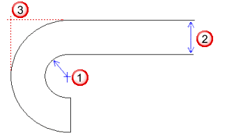
- Select Hem edge, and enter the Radius of the edge
 .
.
If you specify a Radius of 0 for the hem edge, PowerInspect saves the group as an edge-point inspection group.
- Enter the thickness of the surface
 in the Edge box of the Default offset area. If the surface is to be probed from the top, enter the offset as a positive value. If the surface is to be probed from the bottom, enter the offset as a negative value.
 The nominal position of the hem edge
 is calculated as the sum of the Radius and the Edge values.
 - Complete the inspection group settings, and then click OK to save your changes. The CAD view is shown in full-screen mode, and the Hem Edge Points on the Fly dialog is displayed.
- Probe a point on the part surface nearest the edge you want to inspect. The coordinates of the point are displayed on the left of the Hem Edge Points on the Fly dialog.
- Probe a second point against the edge. A bar is shown at the bottom of the Hem Edge Points on the Fly dialog to indicate the proximity of the probe to the edge location determined by the first point. The colour of the dL value indicates whether the point is within tolerance (green), below tolerance (blue), or above tolerance (yellow).
- Click
 to save the edge point measurements and probe the next edge point.
 - Repeat steps 6 to 8 to measure more edge points.
- When you have finished probing, click
 to save the points and close the dialog.