The CAD view displays:
- The first collisions and out-of-bounds moves in a probe path.
- All illegal and missing contacts in a probe path.
The faults are displayed using a combination of colour-coded lines and symbols; the colour coding is the same as that used for path-status icons shown in the inspection sequence:
- Yellow— Out-of-bounds move
- Orange— Collision
- Blue— Missing contact
- Purple— Illegal contact
- Grey— Undefined probe or probe path
Example:
The following CAD model shows the contact points in two surface inspection groups:
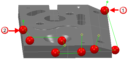
Where:
 shows the start of the first inspection group.
 shows the start of the second inspection group.
When viewed in the CAD view, the following verification colours and symbols are shown:
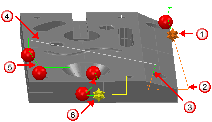
A fault symbol and probe path in orange indicates a collision.
The probe path continues in orange to indicate another collision. The collision symbol is only displayed for the first collision in a path, so no symbol is shown.
 The path changes to green to indicate no fault was found in this section.
 The path changes to grey to indicate this section is unverified.
 The path for the second surface inspection group is green to indicate no faults were found.
 The yellow symbol indicates an out of bounds move. The path is also shown in yellow.