Use the Flowline finishing page to create a toolpath from patterns. The pattern must contain several segments, typically two drive curves and two limit curves.
- On surface — Uses the surface of the model to calculate the stepover. This option can detect and machine undercuts. You must choose an Embedded pattern.
- Tool tip — Considers the tool's cutting geometry when calculating the stepover. This option is useful for machining areas where the tool cannot contact all the points on a surface because of the shape of its cutting geometry. For example, an area where the internal corner radius is smaller than the tool's radius. You must choose a
Start curve and an
End curve and select the
Machined Surfaces.
Note: The Tool Tip option does not currently support the machining of undercuts.
Curves definition — Specifies the curves bounding the area you want to machine and adds the machining properties to those curves.
-
Embedded pattern
 — Select a pattern from the list. If no pattern is displayed, or
 is selected, then no pattern is selected. The list contains a list of all available patterns. Since flowline toolpaths are created from embedded patterns, only the embedded patterns are listed here.
-
 Select picked pattern — Click to select a pattern by picking in the graphics window, rather than by name in the
Select pattern list.
Note: Clicking displays the
Pick Entity tab. Select a pattern in the graphics window to close the
Pick Entity tab and display the pattern in the
Selected Pattern field.
Select picked pattern — Click to select a pattern by picking in the graphics window, rather than by name in the
Select pattern list.
Note: Clicking displays the
Pick Entity tab. Select a pattern in the graphics window to close the
Pick Entity tab and display the pattern in the
Selected Pattern field.
-
Curve definition
 — Specifies:
- the drive curves
- the limit curves
- any intermediate curves
- the machining strategy.
-
Status — Summarises the current status of the selected curves, and is updated automatically as curves are selected. You need to reselect curves if Valid is not displayed.
Start curve — Select a pattern to define the start of the toolpath. The curve does not need to be an embedded pattern. The toolpath bends between the Start curve and the End curve.
End curve — Select a pattern to define the end of the toolpath. The curve does not need to be an embedded pattern. The toolpath bends between the Start curve and the End curve.
Machined surfaces — Select a level or set to define the surfaces to be machined.
- One way — The tool can only cut in one direction.
- Two way — The tool can cut in both directions.
For more information, see Raster ordering.
Spiral — Select to produce a spiral toolpath. This minimises the number of lifts of the tool and maximises cutting time while maintaining more constant load conditions and deflections on the tool.
Sequence — Select the sequence of toolpath segments.
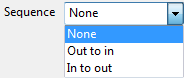
- None — The raster type movement is maintained.
- Out to In — The toolpaths are transformed from a raster-type movement to a constant -Z or spiral-type movement.
- In to Out — The toolpaths are transformed from a raster-type movement to a constant-Z or spiral-type movement.
Tolerance — Enter a value to determine how accurately the toolpath follows the contours of the model.
Surface joining tolerance — Enter a value to disassociate the machining tolerance from the tolerance used to define what is a gap between surfaces. If the gap between surfaces is larger than the machining tolerance, PowerMill creates two toolpath segments. To ensure one continuous toolpath across a gap, use a larger Surface joining tolerance.
Thickness — Enter the amount of material to be left on the part. Click the
Thickness
 button to separate the
Thickness
box in to
Radial thickness
button to separate the
Thickness
box in to
Radial thickness
 Axial thickness
 . Use these to specify separate
Radial and
Axial thickness as independent values. Separate
Radial and
Axial thickness values are useful for orthogonal parts. You can use independent thickness on sloping walled parts, although it is more difficult to predict the results.
. Use these to specify separate
Radial and
Axial thickness as independent values. Separate
Radial and
Axial thickness values are useful for orthogonal parts. You can use independent thickness on sloping walled parts, although it is more difficult to predict the results.
Radial thickness — Enter the radial offset to the tool. When 2.5-axis or 3-axis machining, a positive value leaves material on vertical walls.
Axial thickness — Enter the offset to the tool, in the tool axis direction only. When 2.5-axis or 3-axis machining, a positive value leaves material on horizontal faces.

Stepover — Enter the distance between successive machining passes.
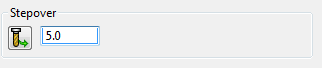
 Copy stepover from tool — Click to load the radial depth of cut from the active tool's cutting data. The radial depth of cut is measured normal to the tool axis.
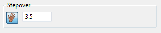
 Edited — When displayed, shows value entered by you (or another user). Click
to change this value to the automatically calculated value. Click
to change this to the automatically calculated value.
Edited — When displayed, shows value entered by you (or another user). Click
to change this value to the automatically calculated value. Click
to change this to the automatically calculated value.
- Stepover — Enter the distance between successive machining passes.
If you enter a Stepover value then
changes to
.