Use this dialog to:
- Create dimensions of holes (ordinate dimensions).
- Create overall item dimensions (default dimensions).
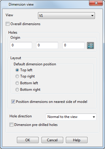
View — Select the view from the list, or click inside the required view in the drawing.
Overall dimensions — Select this option to display the X and Y dimensions on the item in the selected view, if the dimensions do not already exist.
Holes:
Origin — The origin is set to the view origin by default. If you change the origin, the view origin updates to the new position. The origin is marked by centrelines.
To change the origin:
Enter the
X Y Z
coordinates, or click the
Position
 button to open the
Position dialog, where you can use position entry tools.
button to open the
Position dialog, where you can use position entry tools.
Layout — You can choose the layout for the text of the ordinate dimensions at the following positions:
- Top Left (default)
- Top Right
- Bottom Left
- Bottom Right
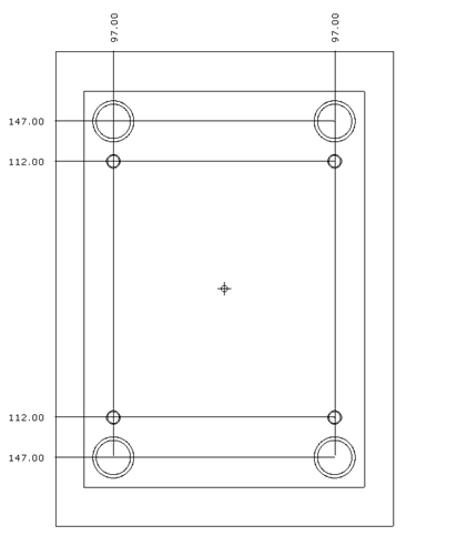
The following example of a view below shows the layout of hole dimensions using the Top Left layout option.
Position dimensions on nearest side of model — Select this option to position the dimension text on the side nearest to the hole centre. This is useful for plates with hundreds of holes, because it improves the clarity of the drawing.
Deselect the option to position all the dimensions on one side; the position of the dimension text is specified by selecting Top Left, Top Right, Bottom Left, or Bottom Right.
Hole direction — Select which holes to dimension:
- Normal to the view — Select this option to include only the holes normal to the view.
- At any angle — Select this option to include holes at any angle.
Dimension pre-drilled holes — Select this option to allow plates with pre-drilled holes to be dimensioned.
If dimensions are close together, the dimension leader lines are drawn doglegged automatically to prevent overlapping.