You can create curves from oblique sections on a surface, solid, mesh or component.
To create an oblique curve:
- Create a workplane.
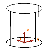
The principal plane of the active workplane is used to define the plane which intersects the surfaces and solids to create the oblique curve.
If no workplane is active, then the principal plane of the world workspace is used.
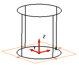
- Position the workplane so that its principal plane is at the angle you wish to create the oblique curve.
- Select the objects.
- Click Wireframe tab > From Selection panel > Oblique Curve.
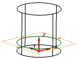
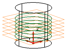
A plane is displayed to show where the oblique curves cut the objects:
- Use the
Oblique dialog to define your oblique curve:

Method
Select one of the following methods to create the curve:
- Select
Distance
and set the distance along the principal axis from the principal plane where you want the oblique curves to cut the objects. If necessary, change the principal axis using the principal plane buttons
 on the status bar.
When you enter a distance, the plane moves to the new position of the oblique curve. Enter a value of 20. The plane moves to reflect the change.
- Select Selected Items to automatically create a Number of sections through the selection.
- Select
Cursor Pick to set the required position for the creation of the oblique sections by selecting a point. The oblique sections are created using the selected point as shown in the model below:
- Select
Curve
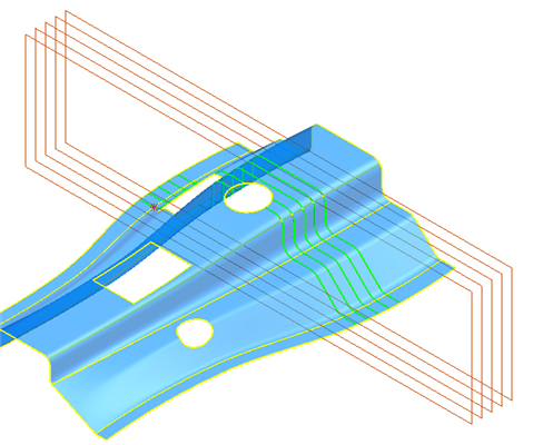
to create oblique curves normal to a 3D drive-curve, at a given distance or with a specified number of sections:
- Select the curve to be used as a drive curve
 .
.
- Adjust the settings on the other options as required. The model below shows ten oblique curves.
- Click
Preview
to view the curves.

- Select the curve to be used as a drive curve
Section settings
Use the following options to create one or more oblique curves from the plane, along the principal axis.- Enter the
Number of oblique curves.

- Enter the
Step to set the distance between each oblique curve. If
Selected items is selected,
Step
cannot be modified.
- Set the distance the oblique curves are
Offset from the objects. The offset is along the plane, on the same side as the surface normal at each point. If the offset is zero, the new curve is dependent on the underlying surface.
An offset value of 5 was used in the example below.

- Select
Trim length to trim oblique curves to the specified length. The oblique curves on the following model have been trimmed to
10.

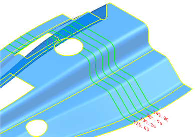
- Select
Display length
to display the length labels as shown below:
- Select
Arc fitting to automatically apply arc fitting to any curves created using the dialog. You can also click the
Arc fitting options
 button to open the
Arc Fitting
dialog.
button to open the
Arc Fitting
dialog.
- Click Apply to generate the oblique curves and continue adding further oblique curves to the objects.
- Select
Distance
and set the distance along the principal axis from the principal plane where you want the oblique curves to cut the objects. If necessary, change the principal axis using the principal plane buttons
- Click OK to accept the changes and close the dialog.