To create a helix:
- Click Wireframe tab > Create panel > Ellipse > Helix.
- Position the cursor and click to enter the point of origin for the helix.
- Use the
Helix dialog to specify the dimensions for the helix curve:
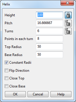
- Enter the overall vertical Height of the helix.
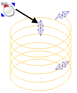
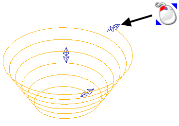
This is measured from the point of origin.Note: Alternatively, change the height of the helix by dynamically dragging the arrow handle at the top of the helix:
Note: The Height, Pitch, and number of Turns are related. If you change one value another value must also change to keep the definition of the helix consistent. - Enter a Pitch value to specify the vertical distance between consecutive turns.
- Enter the number of Turns required in the helix.
- Click the
 button to lock or unlock the Height, Pitch, and number of Turns for the helix.
When a dimension is locked, it does not change when you change another dimension. For example, if the height is locked and you change the pitch, the number of turns changes to keep the definition consistent.
In the example below, the height is 100, the pitch is 16.6, and there are 6 turns:
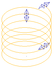
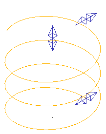
The example below shows the same helix with the height locked and the pitch increased to 30. The number of turns has decreased to maintain consistency:
- Specify the number of Points in each turn.
Increasing the number of points per turn increases the accuracy of the curve that is produced.
- Enter a value to specify the
Top Radius; the radius at the top of the helix.
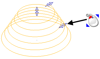
Note: Alternatively, change the top radius of the helix by dynamically dragging the arrow handle at the top of the helix:
- Enter a value to specify the
Base Radius; the radius at the base of the helix.
Note: Alternatively, change the base radius of the helix by dynamically dragging the arrow handle at the bottom of the helix:
- Select Constant Radii to make the base and top radii remain equal.
- Select Flip Direction to flip the direction of the helix between clockwise and counter-clockwise.
- Select
Close Top to create a closed 360
 loop at a constant height around the top of the helix.
- Select
Close Base to create a closed 360 loop at a constant height around the base of the helix.
- Click
OK to apply the changes and close the dialog.
Note: The axis of the helix aligns with the normal of the active workplane.
- Enter the overall vertical Height of the helix.
- To use curve editing options, select the helix to display the Curve Tools tab.