You can fill holes in mesh models using the Fill Hole option and selecting the open boundaries.
If the hole to be filled covers an area of different curvature, split the hole into smaller regions, and fill them separately. This allows more complicated holes to be fixed without the need for full manual triangle-editing. After selecting a hole to fill, you can pick two points on the boundary to split the hole into two regions. If the wrong side is highlighted by default, click to select the region that you want to fill.
Using the model below as an example, fill the hole in two parts, filling the flat area with a planar cap, and the curved area with a curvature cap:
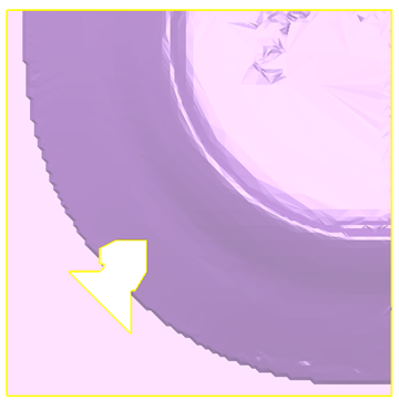
- Select the mesh.
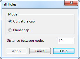
- Click Mesh Tools tab > Fix panel > Fill Hole. The
Fill Holes dialog is displayed:
- Select holes to fill in one of the following ways:
- Box selection:
Use the following key and box selection techniques to select holes to be filled in a selected mesh:
Shift and box selection to add the selection to the set of selected holes.
Ctrl and box selection to invert the selection status of holes intersected by the box.
Box selection without Ctrl or Shift adds holes intersected by the box to the set of selection holes. All holes that are not intersected by the box are removed from the selection.
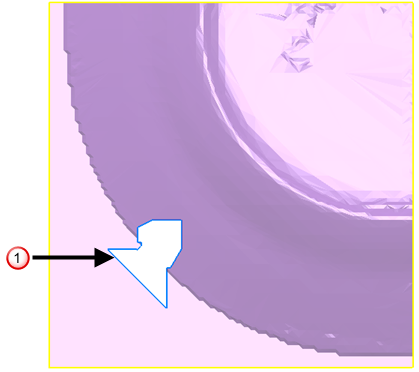
- Boundary selection:
- Select the hole by clicking its boundary
 . The selected boundary turns blue:
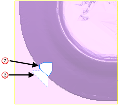
- Select two points to specify part of hole you want to fill first. A mark is added at the position of the first point. A line connects the first point to the second point. The area to be filled is outlined as a blue hole
 . The alternative selection is outlined by a dashed blue line
 . Swap the selection by clicking the outline of the region required:
- Select the hole by clicking its boundary
- Box selection:
- Select one of the following
Mode options:
- Curvature cap calculates the curvature needed to fill the hole by examining the surrounding triangles. New nodes are generated on the curved area. New triangles are generated using the boundary nodes and the new nodes.
- Planar cap generates a nominal plane that passes through the boundary nodes (approximately if the boundary is not planar). New nodes that are within the boundary are generated on the plane. New triangles are generated using the boundary nodes and the new nodes.
The examples below show how important it is to select the correct Mode option. The example shows that in this case, as the hole is on a curved area, you should use the Curvature cap option.
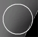 Hole filled with a
Curvature cap
Hole filled with a
Curvature cap
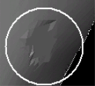
Hole filled with a Planar capThe average length between nodes surrounding the hole is displayed in the Distance between cap nodes. This value is used to determine the density of the new nodes. Change the value as required.
- Click Apply to apply the changes you have made and leave the dialog displayed to continue filling holes.
- Click Cancel when you have finished filling the hole.