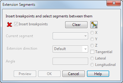
Use this dialog to break the composite curve into smaller segments and use them to define the direction of the laterals in the extension surface.
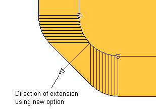
In the diagram below, you can see a segment of an extension surface at a rounded corner:
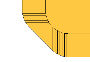
We will show you how to improve this extension surface at the corner using the dialog.
Insert breakpoints — While this option is selected, you can insert and remove breakpoints from the composite curve.
To insert breakpoints, click positions on the composite curve.
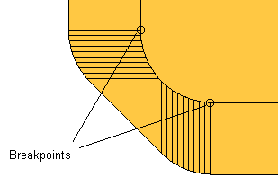
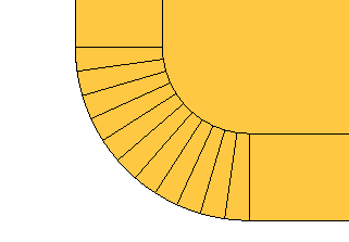
We inserted two breakpoints at the corner:
To remove a breakpoint, hold the Ctrl key and click the breakpoint.
When you have entered the breakpoints, turn off the Insert breakpoints option.
Clear — Click to clear all guide-curves.
 and
and
 toggle — Click to toggle the direction of the breakpoints. For further details, see
Split Segments dialog.
toggle — Click to toggle the direction of the breakpoints. For further details, see
Split Segments dialog.
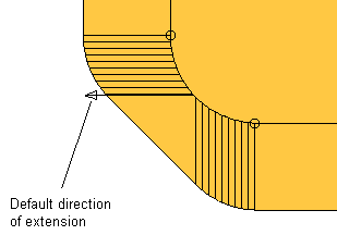
Current segment — Select a segment from the combo box. The segment is highlighted in the model and has an arrow in it giving the default direction of the extension:
Extension direction — Choose a direction from the list:
- Default — Uses the direction as specified on the Surface Extension dialog. You can reverse the direction of the laterals.
- Curve normal — Uses the direction along the normal of the composite curve.
- Along axis — Uses the direction along the specified axis on the dialog.
- Surface internals — Uses the direction along the internal curves of the surface.
When you select an option, the arrow changes to the specified direction.
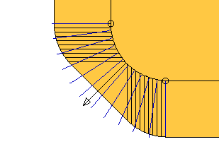
In our example, we choose the Curve normal option:
To reverse the direction of the laterals to the opposite side of the composite curve, click the arrow.
Angle — This is the angle the new surface segment is projected from the existing surface.
Preview — This displays the direction of the laterals in the whole of the extension surface.
OK — Saves the changes and closes the dialog.
To preview the new extensionsurface, you need to click Preview on the Extension Surface dialog.
- if the span has only two points.
- if the existing midpoint is coincident with an endpoint.