- Click Wireframe tab > Create panel > Arc > Fitted.
- Input the first position to define the start of the arc.
You may also select an item to define the start tangent of the arc.
On the screen, a rubber band (in the shape of an arc) is attached to the start point
 and the cursor
 . As the cursor moves, the rubber band moves.
PowerShape is waiting for the next position to be entered.
. As the cursor moves, the rubber band moves.
PowerShape is waiting for the next position to be entered.
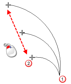
- Input the second position to define the end of the arc.
You may also select an item to define the end tangent of the arc.
Notice that the rubber band is fixed to the two ends of the arc. As you move the mouse, the rubber band displays the shape of the arc as if the cursor is the third position. Also, the radius is displayed and updated as you move the mouse. For smaller increments of the radius, zoom in, for larger increments, zoom out.
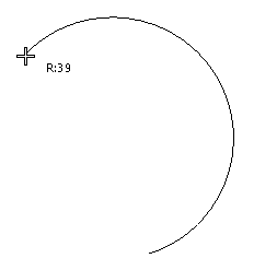
- Input the third position to define a position on the circumference of the arc.
When you input the third position, the Arc Confirm dialog is displayed showing the radius value of the arc:

This dialog enables you to enter correct radius values without moving the start and end positions of the arc. When you create an arc, there may be more than one solution.
- Click
Next Solution to display other solutions.
When using gridding, there may be occasions where the arc radius you require is not snapped to. For example, when working with large grid numbers and the increment between the grid points is 50, you may find it difficult to enter a radius of 3005. This dialog enables you to modify the radius value to 3005.
- Change the radius value of the arc as required.
- Click OK.