To create a solid core from a selection:
- Select the faces.
- Click Solid tab > Create panel > Core from Selection to display the
Solid Core From Selection
dialog:
- Use the options on the Main tab to specify the main settings for the core.
- Use the options on the Advanced tab to specify additional settings.
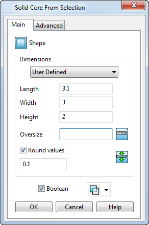
Main tab
Use the settings on this tab to specify the main settings for the core.
- Click the
Shape
button to select one of the following shapes:
 Select this option to define the length, width and height of the core.
 Select this option to define the diameter and the height of the core.
- Use the options in the
Dimensions section to specify the dimensions of the core.
- Choose
User Defined
(default setting) to use set the dimensions of the core to the tightest values enclosing the selected items.
Alternatively, to use previously defined shapes, select an option from the drop-down list. The options on this list are defined in blanks.csv.
- Enter an
Oversize
value to increase the dimensions by the amount you enter. Use
 to toggle between specifying
Oversize
as a measurement or a percentage.
to toggle between specifying
Oversize
as a measurement or a percentage.
Entering an oversize value of 0 reverts the dimensions to the tightest values enclosing the selected items. This is the same as choosing User Defined in the drop-down list
- Select
Round values to round the dimension values.
For example, if the length of the core is 10.367 and Round values is selected with a rounding value of 0.5, the length is rounded to 10.5.
- Use the drag handles to change the size of the core. You can enter an exact value in the box that is displayed when you have dragged instrumentation when creating a
Core from selection.
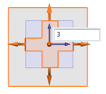
You can define how use of the graphical drag handles is applied. If
 is displayed, the opposite side of the core are also updated when the handle is dragged.
If
 is displayed, the opposite side of the core is not updated.
Note: Information on blanks.csv is included in the Electrode section of the Reference Help. - Choose
User Defined
(default setting) to use set the dimensions of the core to the tightest values enclosing the selected items.
- Use the
Boolean
option to control whether the core is Boolean subtracted or Boolean intersected with the selected faces.
- Deselect this option to create a solid core as a primitive solid.
- Select this option to create a solid with a Boolean feature.
Note: The Boolean section does not appear if the selected items are not faces of a solid.
Advanced tab
Use the options on the Advanced tab to specify additional settings.
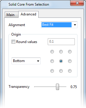
- Select
Best Fit
or
Workplane
from the
Alignment
drop-down list.
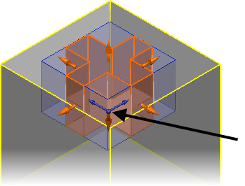
If you select Best Fit, the Z-axis of the core is aligned with the Z-axis of the active workplane, but it is rotated to produce the tightest bounding box around the selected items.
- Use the
Origin
options to specify the origin position of the primitive solid:
- Round values — Select this option to round the values and enter the rounding factor.
- Use the grid to position the origin of block.
- Use the drop-down list to specify the location of the origin:
Bottom — The origin is at the minimum Z coordinate of the solid.
Top — The origin is at the maximum Z coordinate of the solid.
- Use the Transparency slider to specify the transparency of the faces of the graphical preview of the core.