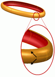
To create a bead surface; a surface that bulges, using a wireframe object:
- Select the wireframe.
- Click Surface tab > Create panel > Bead Surface.
- Use the
Bead Surface dialog to create a bulge:
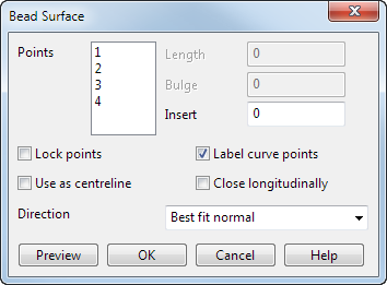
Points — The number of points in this list corresponds to the points on your wireframe. At each point, you can specify the chord length of the arc and the bulge distance. You can select more than one point and specify the parameters for the selection.
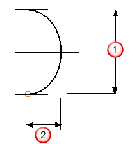
 Length — Enter length of the chord for selected points.
 Bulge — Enter bulge distance for selected points.
- Insert — Insert a point between two existing points. The Points list and the labels on the curve are renumbered accordingly. This means you can specify more precisely the shape of the bead surface between two points.
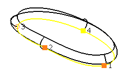
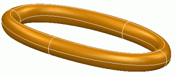
In the example, there are four points. Values have been entered to specify points 1, 2, and 4.The position of point 3 is obtained by interpolation.
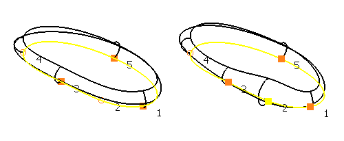
Entering a value of 1.5 into Insert, creates another point between point 1 and point 2. The points are then relabelled, so that the inserted point is point 2. You can modify the Length and Bulge parameters for the new point to control the shape of the surface more precisely.
Lock points — This option is deselected by default until you enter a Length or Bulge value. Deselect this option to obtain the Length and Bulge at this point by interpolating the values of the locked points. The end points of open curves are locked by default.
Label curve points — Select this option (selected by default) to display the original curve with point numbers by each point marker. Deselect this option to hide point numbers.
Use as centreline —Select this option to create a bead surface either side of the centreline along the curve.
Close longitudinally —Select this option to create a closed bead surface in the longitudinal direction.
Direction — Select an option from this list to specify the direction of the surface creation.
- Normal — Align surface to underlying wireframe normals.
- Best fit normal
—Select this option to create a bead surface from a non-planar curve that is the best fit for the normal of the curve.
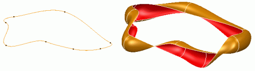
The example below shows the bead surface with the option deselected.
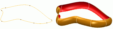
This example shows the difference when the option is selected.
- Radially — Set direction radially outwards from wireframe.
- Align to axes — Set direction to axis in principal plane.
Preview — This displays the surface using the given parameters. If the resulting surface is not correct, change the parameters and click Preview again. The instrumentation at point 1 can be used to reverse the direction of the bulge.

- Click OK to create the surface.