You can split a solid into core, cavity, sliders and internal features (such as holes):
- Select the solid to separate.
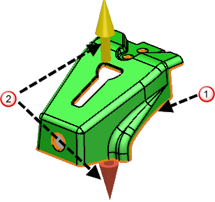
- Click Wizard tab > Part Splitting panel > Separate Solids to display the automatic split line
 and the draw directions for the part
 :
:
- Use the Solid Core/Cavity Separation wizard to split a solid into core, cavity, sliders and internal features (such as holes).
When using Solid Core/Cavity Separation:
- solids are split based on the natural horizons from looking down the Z axis of the active workplane.
- parts are automatically split into core/cavity groups.
- you can move faces between different groups.
- any number of split directions can be used to define sliders.
- you can edit the split line by sketching new wireframe and dividing the relevant faces. The new faces can then be assigned to the relevant split group.
Use the options on this wizard to:
- simulate the separation of the core and cavity of a solid using the slider
.
- control the draw direction
.
- shade the core and cavity
 .
.
- create wireframe from the split line.

Draw direction
Use the options in this section to make changes to the draw direction:
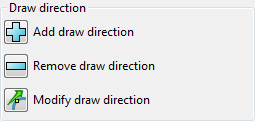
 Add draw direction
- Click a face to be used to define the draw direction.
- Click
to display the
Select draw direction toolbar.
- Use the toolbar to define the draw direction.
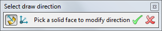
 — Select a normal face to be used to define the draw direction.
 — Select a workplane and use one of the principal axes to define the draw direction.
 — Accept the current draw direction.
 — Cancel the creation of an additional draw direction.
 Remove from draw direction
— Click this button to remove the selected draw direction. Any faces being extracted along this draw direction become ambiguous.
Remove from draw direction
— Click this button to remove the selected draw direction. Any faces being extracted along this draw direction become ambiguous.
 Modify draw direction — Select a draw direction and click this button to display the
Direction
dialog. Use this dialog to modify the selected draw direction.
Modify draw direction — Select a draw direction and click this button to display the
Direction
dialog. Use this dialog to modify the selected draw direction.
Shading
Use the options in this section to modify the shading of the core and cavity.
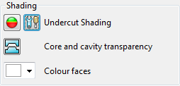

 Undercut shading — Click
to toggle undercut shading. In the Core/Cavity Separation wizard, undercut shading works slightly differently from standard undercut shading.
Undercut shading — Click
to toggle undercut shading. In the Core/Cavity Separation wizard, undercut shading works slightly differently from standard undercut shading.
The areas highlighted in red are undercut with respect to the draw direction they will be extracted along; faces that cannot be extracted along either draw direction will be coloured red.
 Core and cavity transparency — Click this button to toggle the transparency of the core/cavity faces. This lets you see internal features more clearly in relation to the core and cavity.
Colour faces — Use the drop-down list to choose the colour of the faces to be extracted along the current draw selection.
Create wireframe from split line — Select this option to create the wireframe along the split line.
Retain face colours — Select this option to use the wizard colours on the faces after splitting.
 — Click this button to re-calculate the split line and face classification. This may be required if you have made a lot of changes to the model or the draw direction.
 — Click this button to access other
PowerShape functionality whilst remaining inside the Solid Core/Cavity Separation Wizard. This means that you use a range of operations including:
— Click this button to access other
PowerShape functionality whilst remaining inside the Solid Core/Cavity Separation Wizard. This means that you use a range of operations including:
- creating wireframe.
- using solid editing and Direct Modelling tools to divide faces.
Use the buttons on the Split faces toolbar to re-enter the wizard:
— Accept the changes you have made and re-enter the wizard.
— Cancel the changes you have made and re-enter the wizard.
Finish — Click this button to split the part and close the dialog.
Cancel — Click this button to undo all the changes you have made and close the dialog.