Use this dialog to create a split surface.
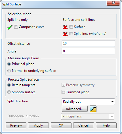
Selection Mode - To add objects to a selection mode, turn on a mode and then select the objects:
- Split line only — Use the Composite curve mode to select the composite curve for the method of creating a split surface by offsetting a split line. The Composite curve option is preselected if a composite curve is present in the model. You can then select the required composite curve, if it is not already selected.
- Surface and split Lines — Use the Surface and Split lines (wireframe) modes to select the surface and wireframe for the method of creating a split surface by fitting a surface to split lines. There are no other options on this dialog for this method.
The rest of the dialog contains options for the method of creating a split surface by offsetting a split line.
Offset distance — This is the distance of the second side of the split surface from the split line.
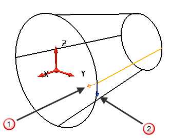
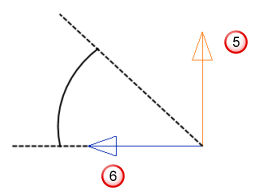
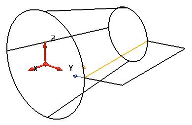
Angle — This is the angle of the second side of the split surface from the split line. Two arrows are drawn at right angles (normal) to the composite curve and are used to measure the angle. The direction of the arrows is determined by the Measure Angle From options.
Measure Angle From — You can create the split surface relative to either the principal plane or the normal of the underlying surface. The directions of the two arrows on the split line are determined by these options:
- Principal plane — One arrow points parallel to the principal plane
 and the other parallel to the axis normal to the principal plane
 .
.
The angle is measured from one arrow to the other as shown below:
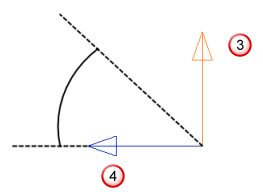
 Arrow pointing along the axis normal to the principal plane.
 Arrow pointing parallel to the principal plane.
You can change the direction of the arrows by clicking them or typing one of the following commands in the Command window:
REVERSE PROFILE — reverses the 'normal' direction instrumentation arrow.
REVERSE WITHDRAWAL_DIRECTION — this reverses the withdrawal direction instrumentation arrow.
The arrow parallel to the principal plane determines the direction of the laterals in the split surface. You can set its direction using the Split direction options.
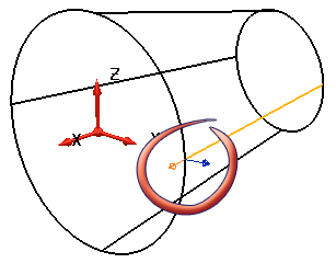
- Normal to underlying surface
— For this option to be available, the composite curve must be created from the underlying surface.
One arrow points along the normal of the underlying surface and the other parallel to the tangent of the underlying surfaces.
In this example, if you click Normal to underlying surface, the arrows change as shown below.
The angle is measured from the arrows as shown below.
 Arrow pointing along the tangent of the surface.
 Arrow pointing along the normal to the surface.
Click the arrow pointing along the surface normal to change its direction.
Note: The arrow parallel to the tangent of the underlying surfaces affects the direction of laterals in a split surface created at an angle. You can set its direction using the Orthogonal direction options.
Process Split Surface — You can choose whether to retain the tangency across the split surface or smooth out any ripples in the surface. You can also select the following options:
- Preserve symmetry — This preserves the symmetry of the split surface when using the Align to Axes option in the Split Direction drop-down list.
In some cases, the curve may look symmetrical, but the points are distributed differently, especially around the corners where the decisions to change direction are made. This can cause an asymmetric result even with this option enabled.
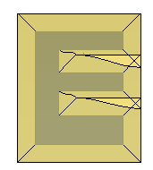
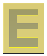
- Trimmed plane — This option is active if the split curve is planar and the composite curve is closed. By default, it is deselected. If you select Trimmed Plane, the bounding box of the split curve is enlarged by the entered Offset distance to define the edge of the trimmed plane. See the example below:
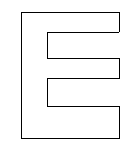
Without the Trimmed plane option, it would be impossible to create a sensible split surface for the curve shown above. This result is shown by the model on the left. The model on the right shows the result when the Trimmed plane option is selected.
Split direction - If you measure the angle from the principal plane, you can set the direction of the laterals within the split surface using one of the following options:
- Align to axes — The laterals of the split surface are parallel to the axes of the principal plane (prior to smoothing). For example, if principal plane is the XY plane, the laterals of split surface run parallel to the X or Y axis. Use this option when the split line is nearly at right angles to the axes.
- Radially out — The laterals of the split surface are normal to the composite curve. Use this option when the model is mostly convex.
- Surface normal — (Option only available if the composite curve has an underlying surface) The laterals of the split surface lie along the normal of the underlying surface projected onto the principal plane. Use this option when the split line is mostly convex.
- Surface internals — (Option only available if the composite curve has an underlying surface) The laterals of the split surface lie in the direction of the internal curves of the underlying surface projected onto the principal plane. This option works well for most shapes, but should be avoided for near vertical edges.
Advanced — This displays the Split Segments dialog. You can use this dialog to break the split line into segments. For each segment, you can then specify the direction of the laterals.
 — Create a
Stepped Split Surface by specifying a number of parameters. Selecting this button displays the
Stepped Split Surface
dialog.
— Create a
Stepped Split Surface by specifying a number of parameters. Selecting this button displays the
Stepped Split Surface
dialog.
Orthogonal direction — When the Normal to underlying surface option is selected and the Angle value is greater than zero, Orthogonal direction affects the direction of laterals of the split surface using one of the following options:
- Principal axis — Uses the axis normal to the principal plane as the direction of the laterals. This option is most useful for surfaces with edges that are trimmed at an angle. You must align the principal axis to the required direction of the split surface. This is done by creating a workplane before creating the split surface and pointing the workplane's principal axis in the direction you want to create the split surface.
- Curve normal — The direction of the laterals lie along the normal of the composite curve. This is the best option for creating split surfaces radially around flat surfaces, or when the composite curve is in the plane perpendicular to the required direction of the split surfaces.
- Surface internals — The direction of the laterals lie along the direction of the laterals and longitudinals of the underlying surface. This option can sometimes get the required result when the other two options fail.
Preview — Displays the split surface created using the current settings in the dialog. You may continue to change the settings in the dialog until you are satisfied with the previewed split surface.
Apply — Creates the split surface and leaves the dialog open.
OK — Creates a split surface and closes the dialog.
Cancel — Closes the dialog and does not create a split surface.