Places a P&ID object’s 3D equivalent in a Plant 3D model.
 Ribbon: Click Home - Piping tab
  Part Insertion panel
  P&ID Line List
 Command entry:
plantpidlinelist
Line List Controls
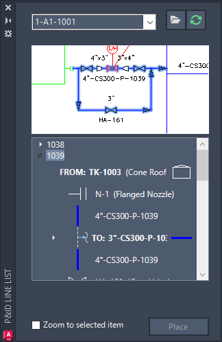
Provides a way to place the 3D equivalents of P&ID lines and inline components in a 3D model.
- Dropdown List
- Displays the name of the current P&ID drawing. By default, the last drawing you opened is displayed.
- Place
- Places the selected line or component in the 3D model.
Line List Panel
Displays the lines and inline components available to be placed in a 3D model.
- Line List Toolbar
- Provides buttons that open and refresh the status of drawings.
-
 Open. Opens the selected P&ID drawing.
-
 Refresh. Refreshes the line list and line components of the selected P&ID drawing.
-
- P&ID Preview
- Provides a preview of the selected P&ID drawing from the dropdown list.
- To change the color of the preview area, right-click the preview area and select Invert Background Color.
- Tree View
- Each node in the tree represents a line group in the P&ID drawing. The inline components, branches, off page connectors, start/end equipment and nozzles associated with each line group are ordered according to the flow direction of the pipeline.
-
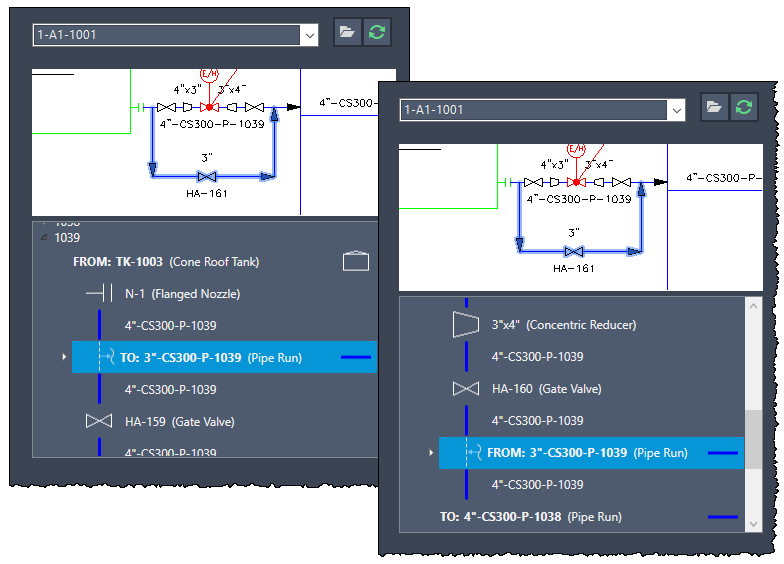
- Branch: Each branch of a line segment is listed in the tree view, with the flow direction clearly identified.
- The branch is represented by an icon and prefix, indicating whether it is an outlet (TO)
 or inlet (FROM)
 .
.
- By expanding a branch, you can view the line segments, inline components, and the start/end points of the branch.

- The branch is represented by an icon and prefix, indicating whether it is an outlet (TO)
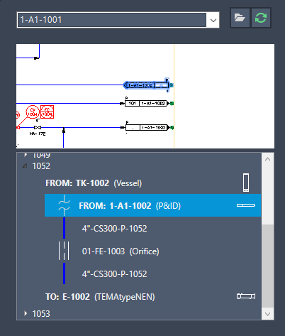
- Off-page connectors (OPC): Off-page connectors are identified with an icon
 and prefix indicating the flow direction, outlet (TO) or inlet (FROM).
- For line groups that are connected by off-page connectors across multiple P&ID drawings, the start/end components from another P&ID drawing are displayed in the tree view.
- To view the connected line segment, double-click the off-page connector.

- Shortcut menu: Each node in the tree has a shortcut menu that offers various functions:
- Place component in current DWG. This option allows you to place the selected component in the current drawing.
- Find in P&ID preview. Enables you to locate and highlight the selected component within the P&ID preview.
- Expand/Collapse. For branch nodes, this option allows you to expand or collapse the branch.
- Show connected P&ID line details in the list. For off-page connectors, this option allows you to view the P&ID details directly in the P&ID Line List.
- Branch: Each branch of a line segment is listed in the tree view, with the flow direction clearly identified.
- Zoom to selected item
- When this check box is selected, you can click an item in the tree and the corresponding object is displayed as large as possible in the center of the drawing area.