After pipe and pipe fittings have been placed in the drawing, you can move connected pipe and change part properties.
If you modify the location, spec, or size of pipe, AutoCAD Plant 3D toolset will attempt to retain pipe connections. If you make a change that cannot be resolved, the connection is marked with a property-mismatch glyph, or it is disconnected.
AutoCAD Plant 3D toolset provides a number of tools you can use to modify pipe.
Substitute Parts
You can use the Substitution grip to replace compatible parts.

A compatible part has the same size and type (for example: you can substitute a gate valve with a ball valve).
Using Alignment Lines to Help Move Pipe
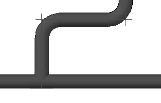
You can use alignment lines as visual tools. When you select pipe in the drawing, alignment lines display along the axis of connected pipe.

Alignment lines help you to identify connected pipe, and to determine which direction you can move the pipe.
When you use a Move grip, you move the pipe axis and all connected parts that share the axis. Conceptually, this is the same as stretching alignment lines with Ortho mode on.
Changing Part Properties
You can use the properties palette to change pipe and fitting properties.
You can change a part in the drawing by modifying the size or spec property. If you change a part, AutoCAD Plant 3D toolset can retain connections by adjusting adjacent fittings. For example: changing the pipe size adds (or removes) reducers.
You can change the property value of multiple items at once. Selecting all connected items before you change size or spec allows you to avoid temporary incompatibilities that can add unnecessary fittings or cause disconnections.
For more information on selecting connected pipe, see Select Piping.
You can also change properties using the Data Manager.
Update a Pipe Spec
You can update the drawing when a change is made to a spec (extension .pspx) file.
Fitting geometry, material properties, and connection type (endcode) are set in the pipe spec. If a part is unavailable in a spec, a placeholder part is used.