Tag formats can include properties that acquire their values from other properties. If the Unit value at the project level changes, all tags with that property as a subpart are updated to reflect that change.
Although pipe line groups are not physical entities, you set up tag formatting for pipe line groups just as you would for any other component.
- On the ribbon, click Home tab
 Project panel
  Project Manager
  Project Setup.
- In the Project Setup tree view, expand Plant 3D DWG Settings.
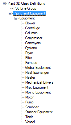
- Continue to expand the list until you locate and click a Plant 3D object (for example: Compressor).
- On the Class Settings pane, under Tag Format, click the tag format type on which you want to base the new tag format (for example:
Equipment Tag [Type-Number]). Click New.
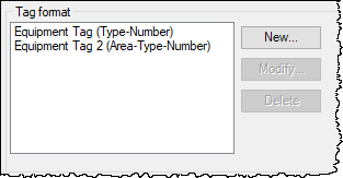
- In the Tag Format Setup dialog box, in the Format Name box, enter the name of the new format (for example:
Equipment Tag [type-number] New).
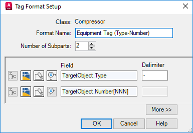
- In the Number of Subparts box, enter a number for how many subparts you want in the tag (for example: 3) or click the Up or Down arrow until the number is displayed.
Tip: Use as many properties as subparts as needed. Use delimiters only between these subparts, not within them. Delimiters appear between the subparts in a tag if you place them in the Delimiter box. Entering a dash between items in the Field box (for example, N-N-N) can produce unexpected results.
- In the first row of icons, click Select Class Properties
 (the first icon on the left).
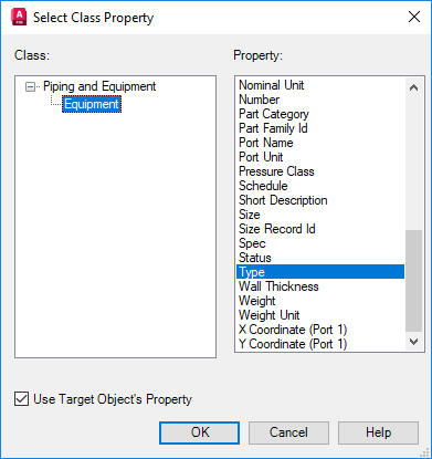
- In the Select Class Property dialog box, do the following:
- Under Class, click Equipment.
- Under Property, click Type.
- Select the check box for Use Target Object’s Property.
- Click OK.
- In the Tag Format Setup dialog box, in the second row of icons, click Select Drawing Properties.

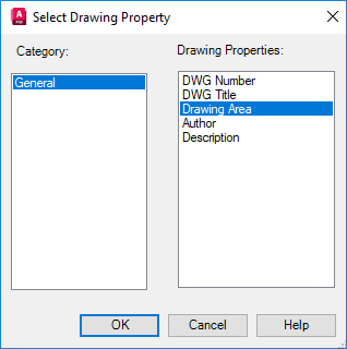
- In the Select Drawing Property dialog box, do the following:
- Under Category, click General.
- Under Drawing Properties, click Drawing Area.
- Click OK.
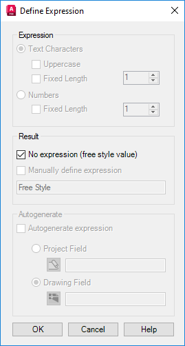
- In the Tag Format Setup dialog box, in the second row of icons, click Define Expression (the last icon in the row).

- In the Define Expression dialog box, under Results, click No Expression (Free Style Value). Click OK.
- In the Tag Format Setup dialog box, in the third row of icons, click Define Expression.

- In the Define Expression dialog box, under Expression, do the following:
- Click Numbers.
- Select the Fixed Length check box. In the Fixed Length box, enter a number or click the Up arrow until the number is displayed.
Note: If the Expression section is disabled: under Result, clear the check box for No Expression (Free Style Value). Then follow the directions in step 14.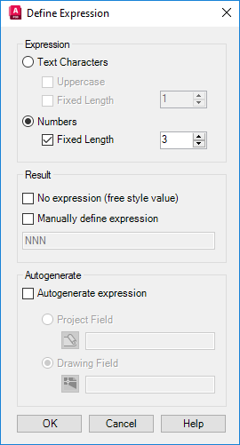
- Click OK.
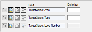
- In the Tag Format dialog box, under Delimiter, enter a delimiter where appropriate. In the example below, a period (.) is used as the delimiter for General.Area[].
Note: Do not place a delimiter in the Field box.
- Click OK.
- On the Class Settings pane, under Properties, in the Property Name column, click TagFormatName.
- In the TagFormatName row, in the Default Value column, in the drop-down list, click the tag format you want to use for tagging the Plant 3D object.
- Click OK.
You created a new tag format and assigned it to a Plant 3D object. When you use the Plant 3D object in a drawing, the Assign Tag dialog box prompts you to enter tag data for the tag format you created in this procedure.