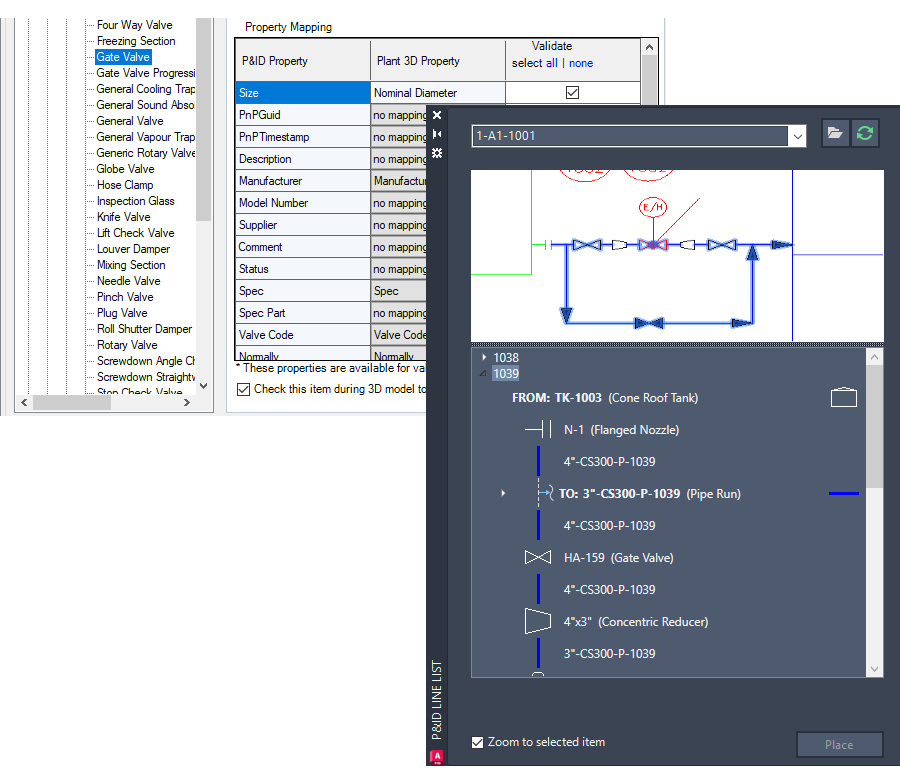
The P&ID line list has undergone a complete redesign and improvement, resulting in the creation of an enhanced P&ID modeler. This new modeler provides a more comprehensive view of the P&ID drawing, displaying all line segments and their associated components such as inline components, nozzles, start/end equipment models, branches, and off-page connectors.
With the P&ID Line List window, you can now easily select any available P&ID object and place its corresponding Plant 3D counterpart in the 3D model. This ensures that the property values of the P&ID object are accurately copied to the 3D model.
Note: For accurate placement of Plant 3D objects in the model, it is highly recommended to map a P&ID object to its corresponding Plant 3D object before placement. If unmapped items are placed, the Custom Parts dialog box is displayed.
P&ID line segments are always mapped to Plant 3D pipes.
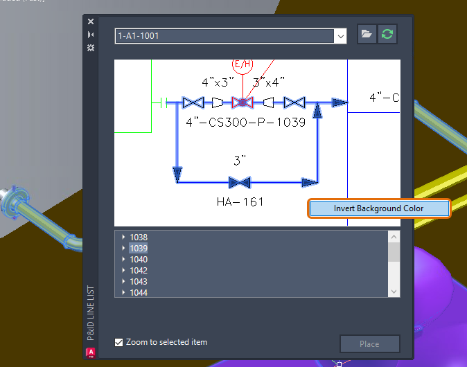
You can customize the background color of the P&ID preview. Right-click the P&ID preview and choose Invert Background Color.
To place these items in the 3D model, choose the desired start or end equipment and nozzle, and map them to their corresponding Plant 3D counterparts.
Once a P&ID equipment is placed in the 3D model, click on a nozzle in the tree view to place it as well. If the nozzle has already been placed in the 3D model, the Edit Nozzle dialog box is displayed. If the nozzle has not been placed yet, the Add Nozzle is displayed instead.
Note: When a specific nozzle tag exists in the Plant 3D equipment template, the property values of all nozzles are copied to the Plant 3D nozzles.