When you plan to perform energy optimization for an architectural model that includes masses and detailed elements, you need to understand how Revit uses these elements to generate the energy analytical model.
When they are set to room-bounding, Revit uses the following elements to create the energy model:
- Ceilings
- Columns
- Curtain panels
- Curtain systems
- Curtain wall mullions
- Doors
- Floors
- Mass
- Roofs: common edges, hidden lines, interior edges, roof soffits
- Shaft openings
- Structural columns
- Walls: common edges, hidden lines
- Windows
To enable the creation of a complete energy analytical model, the Revit project must meet 2 requirements:
- The building elements must be reasonably enclosed. The model does not need to be watertight. Small gaps and overlaps are natural part of real architectural models. They are expected and allowed during the creation of the energy analytical model.
- The settings for Analytical Space Resolution and Analytical Surface Resolution are adjusted to suit the level of model detail.
In addition, read the following information for hints on achieving a complete and reasonable energy analytical model.
Rooms and spaces
The architectural model does not need to contain room elements or space elements for the creation of an energy analytical model. The 3D geometry that forms analytical spaces and surfaces is generated directly from the architectural elements, independent of rooms or spaces in 2D or 3D.
If the architectural model contains rooms or spaces that reside within analytical spaces of the energy analytical model, the analytical spaces adopt the room/space data. Use the Room/Space Export Category setting of the Advanced Energy Settings dialog to specify whether room data or space data is used in this case. See Advanced Energy Settings.
Generate Energy Analytical Model by View
In a 3D view, you can display elements of interest using a section box, view filters, Visibility/Graphic Overrides, etc. In the Energy Settings dialog, enable Use Only Elements Visible In Current View setting Energy Settings. The currently active view will be used as a filter to generate the energy analytical model. Only elements visible in the view are included.
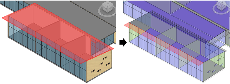
Shading
Revit does not have an architectural element category for shading. Instead, it has an Analytical Model category: Analytical Surfaces type: Shades. These shade elements cannot be created manually. Instead they are created as part of the energy analytical model as follows:
- where elements or parts of elements are external to the building
- where conceptual masses exist without mass floors
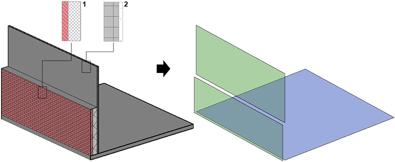
Sandwiched elements
Two or more elements are sandwiched when they run parallel or close to parallel and within one or two times the Analytical Space Resolution setting. In these cases, a separate analytical surface of the appropriate type is created. If the separate sandwiched elements have material thermal properties, they are translated into an appropriate set of constructions, layers, and materials data in the gbXML, DOE2 and EnergyPlus files.
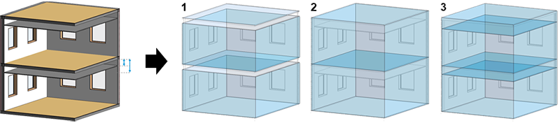
Ceiling voids
During energy analytical model creation, ceilings are treated like other building elements to create analytical surfaces. Analytical spaces are also created to represent the ceiling voids.
The following example shows a typical false ceiling arrangement, the depth of which varies from case to case. Depending on this depth and the Analytical Space Resolution setting, the treatment of each ceiling void is the result of one of 3 conditions:
- Less depth or less resolution: No separate analytical spaces are created for ceiling voids.
- Room-bounding is disabled for ceiling panels: No separate analytical spaces are created for ceiling voids.
- Greater depth or greater resolution: Separate analytical spaces are created for ceiling voids and will be simulated as such when the average depth is less than 6.5' (2m).
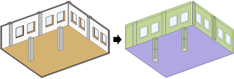
Columns
During energy analytical model creation, columns are treated like other building elements to create analytical surfaces. However, depending on their size and detailed geometry, columns may not be relevant to the energy simulation.
In the following example, the exterior columns form a reasonable part of the exterior walls. However, the interior columns reduce usable floor area, which impacts other energy data such as lighting and equipment power density. The extent to which columns are accounted for depends on the nature and size of the columns and the Analytical Space Resolution setting.
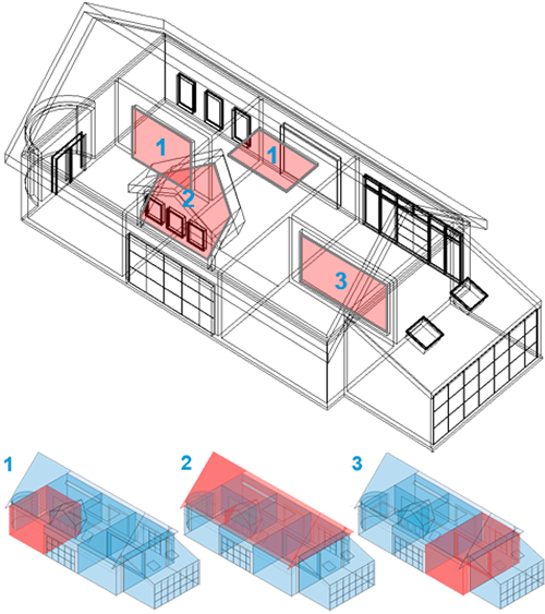
Openings and edited profiles
During energy analytical model creation, Revit openings (by Face, Shaft, Wall, Vertical, and Dormer) are treated like other building elements to create analytical surfaces with one difference: these elements create Analytical Surface: Air Openings.
When profiles of building elements are edited, however, these surfaces are seen to be open (not enclosed), and the behavior of analytical space creation will be different.
The following illustration provides 3 examples of this behavior:
- Revit Opening by Face, Shaft, Wall or Vertical: Separate analytical spaces with a surface type of Air Opening
- Dormer opening: No separate analytical space or surface type of Air Opening
- Edited profile: No analytical space separation
Linked models
During energy analytical model creation, elements from linked models are used if the linked model is set to room-bounding. See Use Room Boundaries in a Linked Model.
Design options
The energy analytical model uses architectural elements from the main model and the primary design option.
To study another design option, in the Design Options dialog, use the Make Primary tool to reset the primary design option. Then recreate the energy analytical model.
If you are using design options for construction documents, you cannot change the primary option because annotations would be compromised.