System-Zones are graphic elements that are used to designate areas of the building that will be served by specific analytical systems and zone equipment.
When you create the energy analytical model, analytical spaces are added to all enclosed volumes in the 3D geometry. Every analytical space is assigned to any System-Zone that it is inside or touching. The relationship is displayed in the System Browser.
To add a system-zone
- Click Analyze tab
 Energy Optimization panel System-Zone
 .
.
Sketch mode is enabled.
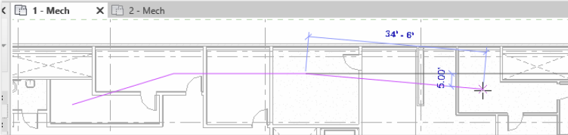
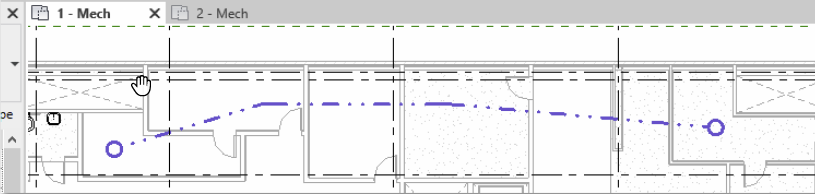
- Draw lines and shapes as needed through every room that should be included in an area served by a specific analytical system. Any room or space that is touched by the line is included.
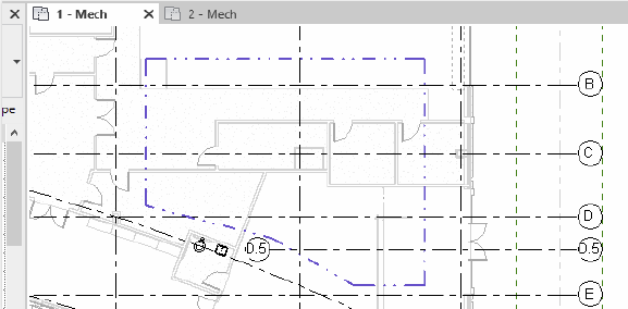
- Click Finish to end the edit mode.
The System-Zone is placed. To override the display settings, on the Analytical Model Categories tab, use the Visibility/Graphic Overrides dialog.
- Select the System-Zone to view its properties and assign zone equipment.
You can add a System-Zone as a 2D shape, using the tools available within
Sketch mode. Anything inside the shape or touching the shape will be part of the System-Zone.
Note: You can edit the Level Offset parameter in the Properties palette for a selected system-zone to move it to the proper offset. The default value is 4 feet or 1.2 meters.