Modify type properties to change a stair family's construction, end connections, supports, and more.
Stair Types
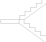
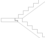
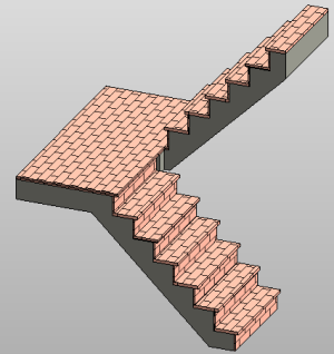
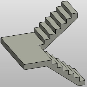
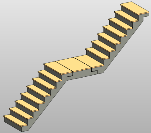
When you create a stair, you select a stair type from 3 predefined system families: Cast-In-Place Stair, Precast Stair, and Assembled Stair. The following table illustrates some of the different types of stairs you can create.
| Stair Type | Example |
|---|---|
| Cast-In-Place Stair: Monolithic Run and Monolithic Landing (examples with treads and without treads) |
  |
| Precast Stair: Notch Connection |
 |
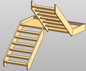
| Assembled Stair: Wood Stair (non-monolithic run and non-monolithic landing) |
 |
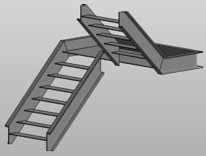
| Assembled Stair: Steel Stair (non-monolithic run and non-monolithic landing) |
 |
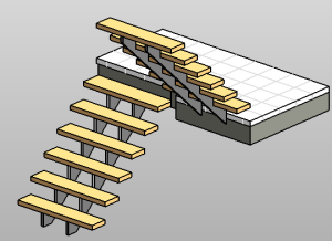
| Assembled Stair: Steel Run and Monolithic Landing (non-monolithic run and monolithic landing) |
 |
Type Properties
To change type properties, select an element and click Modify tab Properties panel
![]() (Type Properties). Changes to type properties apply to all instances in the project.
(Type Properties). Changes to type properties apply to all instances in the project.
| Name | Description |
|---|---|
| Calculation Rules | |
| Maximum Riser Height | Specifies the maximum height of each riser on the stair element. |
| Minimum Tread Depth | Sets the minimum tread width along the center path for all common runs (winder, spiral, and straight). This parameter does not affect the creation of a sketched run. |
| Minimum Run Width | Sets the initial value for the width of a common run. This parameter does not affect the creation of a sketched run. |
| Calculation Rules | Click the button to open the Stair Calculator dialog. See Use the Stair Calculator. |
| Construction | |
| Run Type | Defines the type for all runs in the stair element. |
| Landing Type | Defines the type for all landings in the stair element. |
| Function | Indicates whether the stairs are interior (default value) or exterior. Function is used in scheduling and to create filters to simplify a model when exporting. |
| End Connection (Precast Stair Only) | |
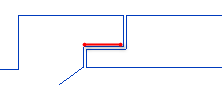
| Connection Method | Defines the join style between a run and landing.
|
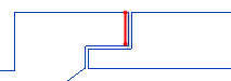
| Notch Extension | Specifies the horizontal length of the notch profile.
 |
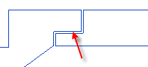
| Notch Thickness | Specifies the vertical length of the notch profile from the top.
 |
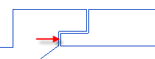
| Horizontal Gap Distance | Specifies the height of the horizontal gap between the run and landing.
 |
| Vertical Gap Distance | Specifies the width of the vertical gap between the run and landing.
 |
| Supports | |
| Right Support | Specifies whether a Stringer (Closed), Carriage (Open), or No right support is created with the stair. A stringer encases the treads and risers. A carriage exposes the treads and risers. |
| Right Support Type | Defines the type of right support used in the stair. |
| Right Lateral Offset | Specifies a value to offset the right support from the edge of the run in a horizontal direction. |
| Left Support | Specifies whether a Stringer (Closed), Carriage (Open), or No left support is created with the stair. A stringer encases the treads and risers. A carriage exposes the treads and risers. |
| Left Support Type | Defines the type of left support used in the stair. |
| Left Lateral Offset | Specifies a value to offset the left support from the edge of the run in a horizontal direction. |
| Middle Support | Indicates whether intermediate supports are used in the stair. |
| Middle Support Type | Defines the type of intermediate support used in the stair. |
| Middle Support Number | Defines the number of intermediate supports used in the stair. |
| Graphics | |
| Cut Mark Type | Specifies the cut mark type displayed in the stair. See Modify the Cut Mark for Stairs. |
| Identity Data | |
| Type Image | Assign an imported or view rendering image to the type. |
| Keynote | Adds or edits the element keynote. Click the value and then click the browse button to open the Keynotes dialog. See Keynotes. |
| Model | The model type for the element, if applicable. |
| Manufacturer | Manufacturer for the element materials, if applicable. |
| Type Comments | Specific comments on the element type. |
| URL | A link to a web page for the manufacturer or other appropriate link. |
| Description | A description for the element type. |
| Assembly Description | Description of the assembly based on the assembly code selection. |
| Assembly Code | Uniformat assembly code selected from hierarchical list. |
| Type Mark | A value to designate the particular type. This value must be unique for each type in a project. Revit warns you if the number is already used but allows you to continue using it. (You can see the warning using the Review Warnings tool. See Reviewing Warning Messages.) |
| Cost | Material cost. |