A profile family contains a 2-dimensional closed loop shape that you can load into a project and apply to certain building elements.
 Video: Use Profile Families
For example, you can sketch the profile loop for a railing and then use that shape on a railing in your project. Loaded profiles display in the Project Browser.
To create a profile family, open a new family, and sketch a profile using lines, dimensions, and reference planes. After you save the profile family, you can load it and apply it to solid geometry in the project. The different profile family templates define specific conditions or element types, select a family template that best matches your use case.
This procedure describes creating a generic profile shape that is available to multiple building elements in the project. Your specific building and design intentions may differ.
To create a profile
- Click File tab
 NewFamily.
- In the New Family - Select Template File dialog, select a profile template, and click Open.
The Family Editor opens a plan view that includes 2 reference planes. There are no other views available in which to sketch lines.
- If necessary, sketch reference planes for constraining the lines in the profile.
- Click Create tabDetail panel
 (Line), and sketch the profile loop.
- If necessary, click Create tabDetail panel
 (Detail Component) to place a detail component into the profile family.
Tip: You can change the sorting order of any detail components in the family by using the detail component draw order tools.
(Detail Component) to place a detail component into the profile family.
Tip: You can change the sorting order of any detail components in the family by using the detail component draw order tools. - To specify the detail at which the profile family displays in the project, select any of the lines of the profile sketch, and click Modify | Lines tabVisibility panel
 (Visibility Settings).
- Select the desired detail levels (Fine, Medium, or Coarse), and click OK.
Tip: You can specify the detail level for detail components using the same methods.
- On the Properties palette, under Other, for Profile Usage, click in the Value field, and select the profile type.
For example, if you are creating a mullion profile, select Mullion.
Tip: This setting ensures that only relevant profiles are listed when using profiles within a project. For example, when selecting a profile for a mullion, only profiles with Profile Usage set to "Mullion" will be displayed, stair nosing profiles do not display. Profile Usage set to <Generic> will display for all element types.Note: When creating a railing profile, it is a best practice to keep the geometry of the profile centered on the reference planes of the template. - Click Apply.
- Add any dimensions required.
- Save the family.
Examples
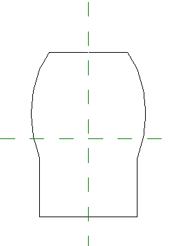
Sample profile sketch
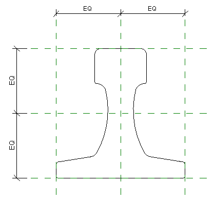
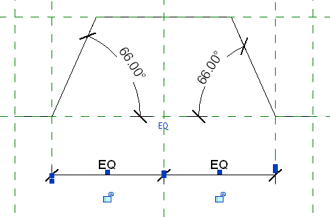
Sample crane rail profile sketch
Sample metal deck profile sketch